


– 24 –
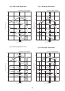
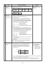
5. CONTROL BLOCK DIAGRAM
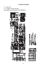
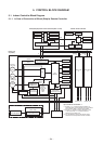
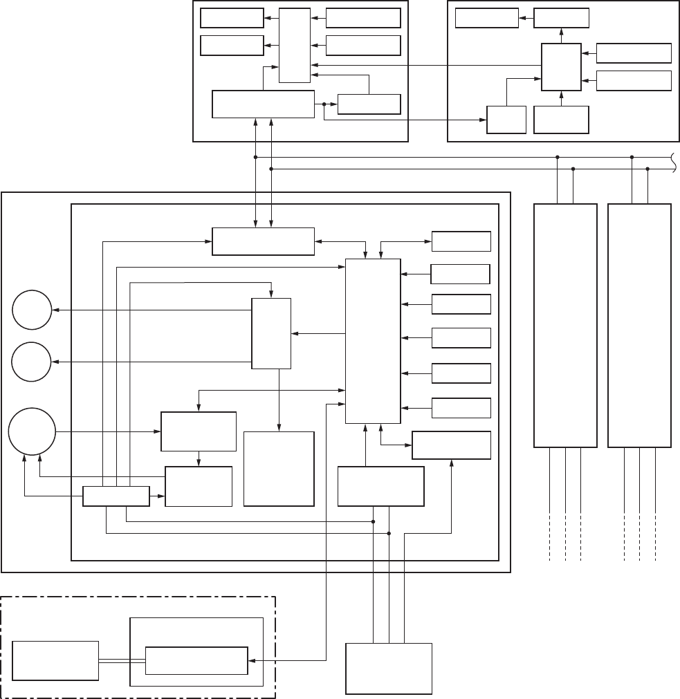
5-1. Indoor Controller Block Diagram
5-1-1. In Case of Connection of Wired (Simple) Remote Controller
Wired (Simple) heder remote controller (Max. 2 units) Central remote controller
Central remote
controller(Option)
P.C. board
(MCC-1440)
∗ “1:1 model” connection interface
(Option)
Outdoor unit
Outdoor unit
321
321
321
Up to 8 units are connectable. ∗1
∗1 However, if “1:1 model connection interface” is
connected when 2 wired (simple) remote controllers
are connected, Max. 7 units are connectable.
∗2 Connect “1:1 model connection interface” to only
1 unit and connect 1 “1:1 model connection
interface” to the header unit.
∗3 It is unavailable to connect the Central remote
controller to the simple wired remote controller.
Same as left
∗2
#3
(Follower)
A B
AB
Same as left
∗2
#2
(Follower)
A B
DC5V
DC5V
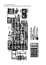
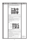
Indoor unit
#1 (Heder)
Indoor control P.C. board (MCC-1402)
Louver
motor
Drain
pump
Indoor
fan motor
CPU
H8/3039
Driver
DC12V
DC5V
DC20V
External
output
Remote controller
communication circuit
Display LCD Function setup
Key switch
CN2
CN1
∗3
CPU
Display LED
Display LCD LCD driver
CPU
Remote controller
communication circuit
Function setup
Key switch
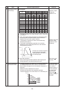
Power circuit
Power circuit
DC280V
Fan motor
control circuit
CPU
TMP88CH47FG
(TMP88PH47FG)
EEPROM
TA sensor
TC sensor
TCJ sensor
Float input
HA
TCC-LINK
communication circuit
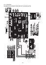
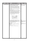
Run
Alarm
Defrost
Thermo. ON
COOL
HEAT
FAN
Serial send/
receive circuit
AC
synchronous
signal input circuit
Power
circuit
Secondary
battery
Outdoor unit
32
1
U3
U4
*
None for
Duct type
*
Option for
Ceiling type