


RGM Form 421, Mfg No. 150492, Page 5
6. Instructions for Reversing Air Flow
by Changing Directional Air Baffles
in the Heat Exchanger
Duct furnaces are equipped with directional air baffles between the
heat exchanger tubes. Facing the control compartment of the furnace,
the standard direction of air flow is from the rear of the furnace (gas
valve location) toward the front of the furnace. If the installation site
requires air flow from the front to the rear, the unit may be field adapted
by re-locating the limit control and reversing the position of the direc-
tional air baffles.
Instructions:
NOTE: If the unit has optional outer side panels, locate the limit con-
trol and remove the outer panel on that side of the furnace.
1.
All Models - Refer to Figure 3A. Remove the screws attaching the
limit control bracket to the side of the furnace. Carefully pull the bracket/
control assembly through the hole. (Do not disconnect wires.)
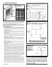
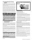
2. All EEDU Models (see below for high CFM HEEDU Models) -
Refer to Figure 3B and follow Steps a)-d) below to reverse the direc-
tion of the baffles.
a) Remove Screws "A". Individually lift each baffle slightly and slide
forward. Remove all baffles completely from the heat exchanger.
b) Remove Screws B and the top baffle support assembly. Re-position
the assembly on the opposite send of the heat exchanger and attach.
c) Remove Screws C and the assembled bottom baffle support and
brackets. Plug the holes in the heat exchanger bottom by re-insert-
ing the screws in the holes. Position the assembly on the opposite
end of the heat exchanger and attach using field-supplied sheet metal
screws.
d) Re-install all of the individual baffles by reversing procedure in
Step a) above.
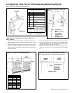
Figure 3B - Model EEDU has a top and bottom
support assembly and individual baffles.
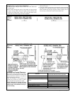
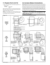
Figure 3A - Limit Control Location - When reversing
air flow, the limit control must be re-located. The
limit control MUST be on the discharge end of the
heat exchanger
NOTE: Actual gas valve
may not be as illustrated.
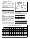
2, depending on the combustion air source as noted in Items 1, 2, and
3 below the illustration.
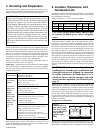
Add total BTUH of all appliances in the confined space and divide by
figures below for square inch free area size of each (top and bottom)
opening.
1. Air from inside the building -- openings 1 square inch free area per
1000 BTUH. Never less than 100 square inches free area for each open-
ing. See (1) in Figure 2.
2. Air from outside through duct -- openings 1 square inch free area
per 2000 BTUH. See (2) in Figure 2.
3. Air direct from outside -- openings 1 square inch free area per 4000
BTUH. See (3) in Figure 2.
NOTE: For further details on supplying combustion air to a confined
space, see the National Fuel Gas Code ANSI Z223.1a (latest edition ).
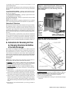
Hazards of Chlorines
The presence of chlorine vapors in the combustion air of gas-fired heat-
ing equipment presents a potential corrosion hazard. Chlorine will,
when exposed to flame, precipitate from the compound, usually freon
or degreaser vapors, and go into solution with any condensation that is
present in the heat exchanger or associated parts. The result is hydro-
chloric acid which readily attacks all metals including 300 grade stain-
less steel.
Care should be taken to separate these vapors from the combustion
process. This may be done by wise location of the furnace with regard
to exhausters or prevailing wind direction. Remember, chlorine is
heavier than air. This fact should be kept in mind when determining
installation locations of heating equipment and building exhaust sys-
tems.
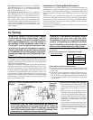
Location of
the
factory-
installed
Limit
Control
Bracket on
a Furnace
with
Standard
Air Flow
Direction
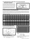
All HEEDU Models (see above for EEDU Models) - Refer to
Figure 3C and follow Steps a) and b) below to move the top
baffle to the entering air end of the heater exchanger.
a) Remove screws B and the baffle.
b) Re-position the baffle on the "entering air" end of the heat exchanger
and attach.