


Form 421, Page 16
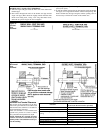
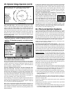
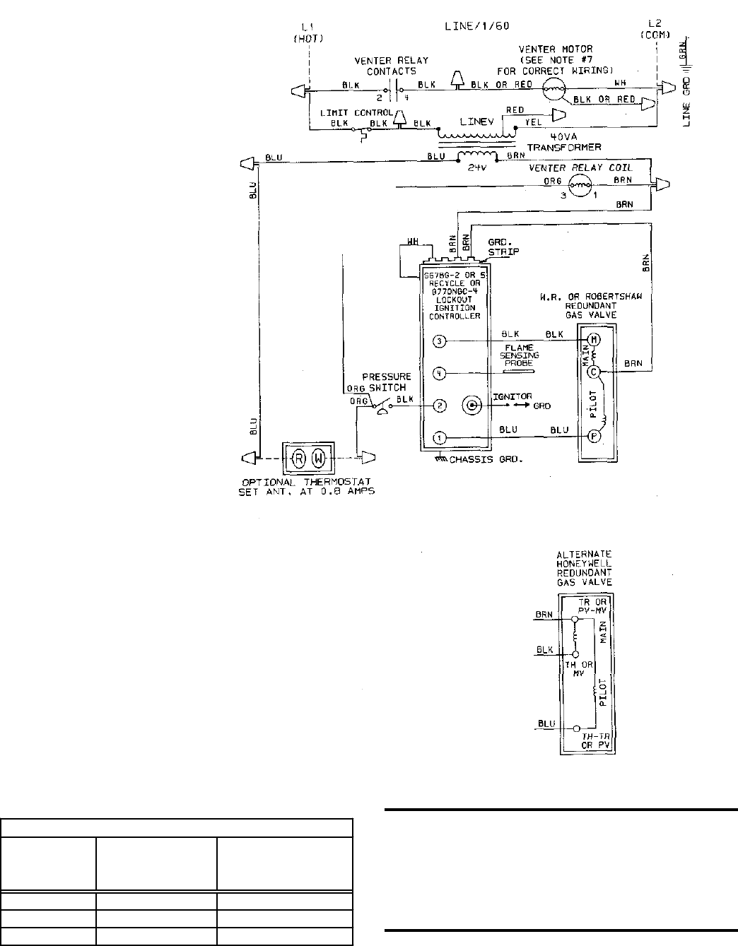
Typical Wiring Diagrams -- Refer to the diagram supplied with the heater for specific
controls or optional equipment.
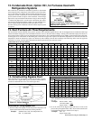
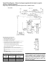
Single-Stage with Intermittent Spark Pilot System with or without Lockout
Field and Replacement Wiring Notes
1. Dotted wiring supplied by others.
2. Thermostat supplied as optional equipment.
3. Use #14 gauge wire for line wiring to unit.
4. Use #18 gauge wire for control wiring.
5. Line and blower motor branch circuit wire sizes should be of a size to
prevent voltage drops beyond 5% of supply line voltage.
6. On 208-230V units, the control transformer has dual voltage primary.
For 208 volt units, use black and red leads (cap yellow).
For 230 volt units, use black and yellow leads (cap red).
On 115 volt units, the control transformer is single voltage primary. Use
black and yellow leads for 115 volt.
Secondary side of transformer (24V), use blue and brown leads.
7. Sizes 75-250, 208 volts, the venter motor wires are black and white (cap
red).
Sizes 75-250, 230 volts, the venter motor wires are red and white (cap
black).
Sizes 75-250, 115 volts, the venter motor wires are black and white.
Sizes 300-400, all voltages, the venter motor wires are black and white.
Field Control Wiring - Length and Gauge
Total Wire
Length
Distance from Unit
to Control
Minimum
Recommended Wire
Gauge
150' 75' #18 gauge
250' 125' #16 gauge
350' 175' #14 gauge
W.D. 110920
CAUTION: If any of the original wire as supplied
with the appliance must be replaced, it must be
replaced with wiring material having a
temperature rating of at least 105
o
C, except for
sensor lead wires which must be 150
o
C. See
Hazard Levels, page 2.