


RGM Form 421, Mfg No. 150492, Page 19
20. Gas Valve
All furnaces are equipped with a 24-volt combination valve which
includes the automatic electric on-off valve controlled by the room
thermostat, the pressure regulator, the safety pilot valve, and the
manual shutoff valve. The standard gas valve allows for single-stage
control from a single-stage, 24-volt thermostat.
WARNING: The operating valve is the prime
safety shutoff. All gas supply lines must be free
of dirt or scale before connecting the unit to
ensure positive closure. See Hazard Levels, page
2.
21. Optional Two-Stage Operation -
Heating Only Application
NOTE: This option is not available on Size 75 using propane gas.
The standard combination control valve is replaced with a two-stage
combination gas control valve providing for low fire or high fire
operation controlled by a two-stage thermostat. First stage (low fire)
is factory set (not field adjustable). Both high and low stages are
controlled by a Servo regulator, maintaining constant gas input un-
der wide variations in gas supply pressure. See instructions packed
with the unit for specific gas valve specifications, wiring, and oper-
ating instructions.
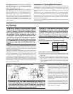
22. Optional Two-Stage Operation -
Makeup Air Application
NOTES: Requires field installed fan control, see Paragraph 19. This
option is not available on Size 75 using propane gas.
Two-stage makeup air units are equipped with a two-stage gas valve,
but instead of control from a two-stage room thermostat, the outlet
air temperature is monitored and controlled by a two-stage ductstat.
When the discharge air temperature drops to the setpoint, low fire is
energized. If low fire cannot satisfy the ductstat setting, high fire is
energized.
Makeup air applications are usually adjusted to discharge an outlet
air temperature between 65
o
F and 75
o
F. In all applications, the al-
lowable temperature rise of the furnace in the installation dictates the
limits of the ductstat temperature setting.
Depending on the option selection, the factory-installed sensor is
either field-connected by capillary tubing to the unit-mounted ductstat
(Option AG3), Figures 18 and 19, or electrically connected to a re-
mote electronic remote temperature selector (Options AG15 or AG16,
Figure 20). The remote temperature selector is available with or with-
out a display module.
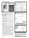
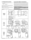
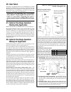
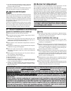
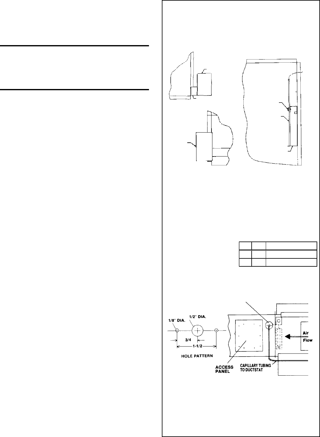
Optional Ductstat with Capillary Tubing (Option AG3) -- The
ductstat is attached to the side of furnace and is connected by capil-
lary tubing to the sensor which is mounted on a bracket on the inner
part of the furnace duct side (See Figure 18). In order to attach the
discharge ductwork to the furnace, the sensor must be removed from
the bracket and the capillary tubing moved out of the way. Follow
the illustrated instructions in Figure 18 for re-connecting the ductstat
after the ductwork is attached.
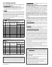
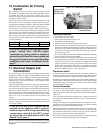
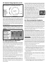
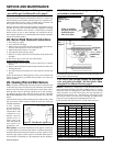
The ductstat dial is illustrated in Figure 19. The dial has an adjust-
able range from 60
o
F to 100
o
F with a fixed differential of 2-1/2
o
F.
Due to different CFM settings and outside air temperatures, the aver-
age downstream outlet air temperature may not match the ductstat
exactly. After the installation is complete, adjust the ductstat setpoint
to achieve the desired average outlet air temperature.
The Sensor and the ductstat are connected by a permanently attached
capillary tubing. In order to attach the discharge ductwork, the sensor
must be removed form the bracket (save the retaining clip) and the
capillary tubing moved out of the way. After the ductwork is attached
to the furnace (See Paragraph 12), a hole must be made in the duct-
work to allow for the sensor to be re-installed on the bracket (capil-
lary tubing with sensor will run through the hole). A removable ac-
cess panel must be provided in the ductwork as shown in Figure 12A,
Paragraph 12.
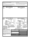
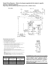
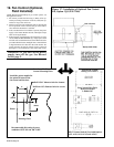
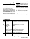
Parts Required and Instructions:
Since the sensor is larger than
the tubing, a gasket and gasket
retainer plate are needed to plug
the hole and protect the capillary
tubing where it passes through
the ductwork. These parts were shipped loose with the furnace. Two
field-supplied sheet metal screws will be needed to attach the plate.
1) Drill the Holes - Refer to the illustration below and select a loca-
tion on the ductwork so that a minimum length of capillary tubing
will be inside the ductwork. Following the pattern, drill holes in
the ductwork.
2) Re-Mount the Sensor on the Bracket - Push the sensor through
the hole. Remove the ductwork access plate. Reaching through
the access hole, use the retaining clip to re-mount the sensor on
the bracket.
3) Install the Gasket - Slide the gasket and hole retainer plate over
the capillary tubing. With the gasket next to the ductwork, attach
the hole retaining plate with field-supplied sheet metal screws (as
illustrated above). Close the ductwork access panel.
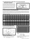
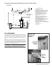
Figure 18 - Ductstat/Sensing Bulb Locations for
Furnace with Option AG3
Side
View
Rear
View
The sensor is mounted on a
bracket on the inner part of
the furnace duct side.
Front
View
The ductstat provided with Op-
tion AG3 is attached to the side
of the furnace at the factory.
Ductstat
Ductstat
Bracket
Ductstat
Bulb
Retaining
Clip
Sensing
Bulb
Sensing Bulb
Bracket
Qty P/N Description
1 7726 Gasket
1 7727 Gasket Retainer Plate