


Form 421, Page 20
22. Optional 2-Stage Operation (cont'd)
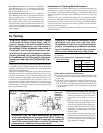
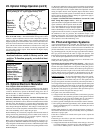
Optional Ductstat with Electronic Remote Setpoint Module (Op-
tions AG15 and AG16) -- The field-installed sensing probe is field-
wired to a remote temperature selector with a temperature operating
range to 130
o
F. The remote modules and a required transformer are
shipped separately for field installation. (Do not wire the remote mod-
ule to the control transformer on the furnace.) Follow the wiring dia-
gram with the unit and the manufacturer's instructions for wiring and
installation. There will be one module for selecting temperature and
one-stage adder module. Option AG16 includes the digital display
module. See Figure 20.
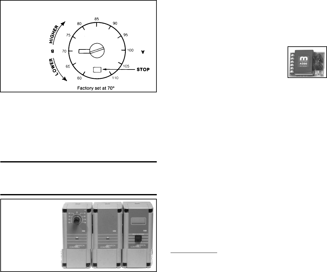
CAUTION: The remote temperature selector
heat/cool selector switch is factory-set in cool
position. To function properly, set switch to heat
position.
Dial has no temperature markings. Pin on adjustment
screw pointing to "B" equals approximately 70
o
F.
23. Optional Electronic Modulation
Note: Requires field-installed fan control.
The type and capability of the electronic modulation system, depends
on the option selected. Electronic modulation options are identified by
a suffix to the Serial No. printed on the heater rating plate. AG7 is
identified as MV-1; AG8 is identified as MV-3; AG9 is identified as
MV-4; and AG21 is identified as MV-A.
Electronic Modulation between 50% and 100% Firing Rate (Op-
tions AG7, AG8, AG9) - Depending on the heat requirements as es-
tablished by the thermistor sensor, the burner modulates between 100%
and 50% firing. The thermistor is a resistor that is temperature sensi-
tive in that as the surrounding temperature changes, the Ohms resis-
tance changes through the thermistor. This change is monitored by the
solid state control center (amplifier) which furnishes varying DC cur-
rent to the modulating valve to adjust the gas input.
Each modulating valve is basically a regulator with electrical means of
raising and lowering the discharge pressure. When no DC current is
fed to this device, it functions as a gas pressure regulator, supplying
3.5" w.c. pressure to the main operating valve.
Refer to the wiring diagram supplied with the furnace for proper wir-
ing connections. Electronic modulation for heating controlled by a spe-
cially designed room thermostat (60
o
-85
o
F) is identified as Option AG7
and is available on unit heater, duct furnace and packaged heater mod-
els. Electronic modulation control systems for makeup air applications
controlled by a duct sensor and temperature selector (55-90
o
F) are iden-
tified as either Option AG8 or Option AG9. The temperature selector
setting for Option AG8 is on the amplifier; Option AG9 has a remote
temperature selector. Both systems are available with an override ther-
mostat. Options AG8 and AG9 for makeup air applications apply to
duct furnace and packaged systems.
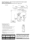
Computer Controlled Electronic Modulation between 50% and
100% Firing Rate (Option AG21) - With this
option the furnace is equipped with a Maxitrol A200
signal conditioner which operates much the same
way as the amplifier above to control the regulator
valve. The conditioner accepts an input signal of
either 4-20 milliamps or 0-10 volts from a customer-
supplied control device such as a computer. With the dip switches on
the conditioner in the "on" positions, the conditioner accepts a 4-20
milliamp signal. In the "off" positions, the conditioner accepts a 0-10V
signal. The conditioner converts the signal to the 0 to 20 volt DC cur-
rent required to control the modulating valve.
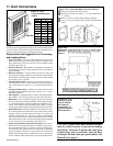
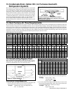
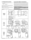
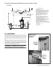
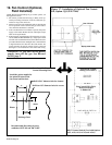
24. Pilot and Ignition Systems
A gas-fired intermittent pilot is standard. The vertical pilot is located
under the aeration panel on the control end of the burner tray and is
accessible only after the burner rack has been removed. Remove the
pilot for maintenance or service, such as checking the wiring and clean-
ing. (See Paragraph 30.) All pilots are target type with lint-free feature.
Pilot gas pressure should be the same as supply line pressure. (See
Paragraph 9.) If required, adjust the pilot flame length to approximately
1-1/4" with the pilot adjustment screw in the control valve body.
NOTE: This model furnace manufactured prior to 11/95 had a hori-
zontal pilot with a spark gap of 7/64".
Intermittent Spark Ignition Safety Pilot Systems -- There are two
types of intermittent spark pilots -- one type shuts off the pilot gas flow
between the cycles and the other not only shuts off the pilot gas flow
between cycles but also has a lockout device that stops the gas flow to
the pilot if the pilot fails to light in 120 seconds. This lockout feature
requires manual reset by interruption of the thermostat circuit. Pro-
pane units require the spark ignition system with the lockout device.
Ignition Controller -- As part of the intermittent safety pilot systems,
the ignition controller provides the high voltage spark to ignite the
pilot gas and also acts as the flame safety device. After ignition of the
pilot gas, the ignition controller electronically senses the pilot flame. A
low voltage DC electrical signal is imposed on the separate metal probe
in the pilot assembly. The metal probe is electrically insulated from
ground. The pilot flame acts as a conduction path to ground complet-
ing the DC circuit and proving pilot flame. With pilot flame proven,
the ignition controller energizes the main gas valve.
If no spark occurs, check the following:
a) Voltage between blue and white terminals (non-lockout type pilot)
and Terminals 2 and 5 (lockout type pilot) on the ignition controller
should be at least 20 volts and no higher than 32 volts. Refer to
Troubleshooting (Paragraph 32) if no voltage is observed.
b) Short to ground in the high tension lead and/or ceramic insulator.
c) Pilot spark gap should be approximately .100". (NOTE: This model
furnace manufactured prior to 11/95 had a horizontal pilot with a
spark gap of 7/64".)
NOTE: When checking for spark with the pilot burner assembly re-
moved from the burner rack, the pilot assembly must be grounded to
the heater for proper spark.
If the above conditions are normal and no spark occurs, replace the
ignition controller.
If the main gas valve fails to open with a normal full size pilot flame
established, check for the following:
a) Voltage between black and brown leads on the main gas valve is 20
to 32 VAC and there is no main gas flow with the built-in manual
valve in FULL OPEN position -- the main valve is defective.
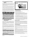
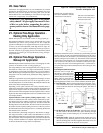
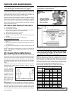
Figure 19 -
Ductstat
Control in
Option AG3
(Mounted in
inverted
position)
Figure 20 - Remote
Temperature
Selector, Stage-
Adder Module, and
Optional Display
Module for Ductstat
in Two-Stage
Makeup Air Control
Options (Option
AG15 or AG16)