


Form 421, Page 4
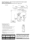
4. Uncrating and Preparation
This furnace was test operated and inspected at the factory prior to
crating and was in operating condition. If the furnace has incurred any
damage in shipment, file a claim with the transporting agency.
Check the rating plate for the gas specifications and electrical charac-
teristics of the furnace to be sure that they are compatible with the gas
and electric supplies at the installation site. Read this booklet and be-
come familiar with the installation requirements of your particular fur-
nace. If you do not have knowledge of local requirements, check with
the local gas company or any other local agencies who might have
requirements concerning this installation. Before beginning, make
preparations for necessary supplies, tools, and manpower.
Check to see if there are any field-installed options that need to be
assembled to the furnace prior to installation.
Option Parts -- Some gas control options will have parts either shipped
loose with the heater or shipped separately. If your unit is equipped
with any of the following gas control options, be sure these parts are
available at the job site.
Other shipped-separate options could include a gas shutoff valve, a
condensate drain fitting, a thermostat, a hanger kit, a coupling kit, a fan
control, or high temperature sealing tape.
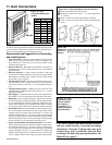
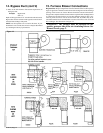
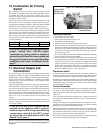
5. Location, Clearances, and
Combustion Air
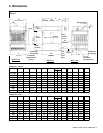
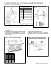
Unit must be installed so that the following clearances are provided for
combustion air space, service and inspection, and for proper spacing
from combustible construction.
NOTE: See Figure 5 for service clearance illustration.
CAUTION: Do not locate heater where it may
be exposed to liquid spray, rain or dripping
water.
These duct furnaces are designed to take combustion air from the space
in which the furnace is installed. The air that enters into the combus-
tion process is vented to the outdoors. Sufficient air must enter the
equipment location to replace the air exhausted through the vent sys-
tem. Modern construction methods involve the greater use of insula-
tion, improved vapor barriers and weather-stripping, with the result
that buildings generally are much tighter structurally than they have
been in the past. The combustion air supply for gas-fired equipment
can be affected by these construction conditions because infiltration
that would have existed in the past may not be adequate. Extensive use
of exhaust fans aggravates the situation. In the past the filtration of
outside air assumed in heat loss calculations (one air change per hour)
was assumed to be sufficient. However, current construction methods
may now require the introduction of outside air through wall openings
or ducts.
WARNING: These furnaces are designed to take
combustion air from the space in which the unit
is installed and are not designed for connection
to outside combustion air intake ducts. Use of
outside air ducts voids the warranty and could
cause hazardous operation. (See Hazard Levels,
page 2.)
Requirements for combustion air and ventilation air depend upon
whether the unit is located in a confined or unconfined space. An "un-
confined space" is defined as a space whose volume is not less than 50
cubic feet per 1000 BTUH of the installed appliance. Under all condi-
tions, enough air must be provided to ensure there will not be a nega-
tive pressure condition within the equipment room or space. A posi-
tive seal must be made in all return-air connections and ducts. Even a
slight leak can create a negative pressure condition in a confined space
and affect combustion.
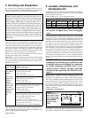
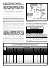
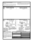
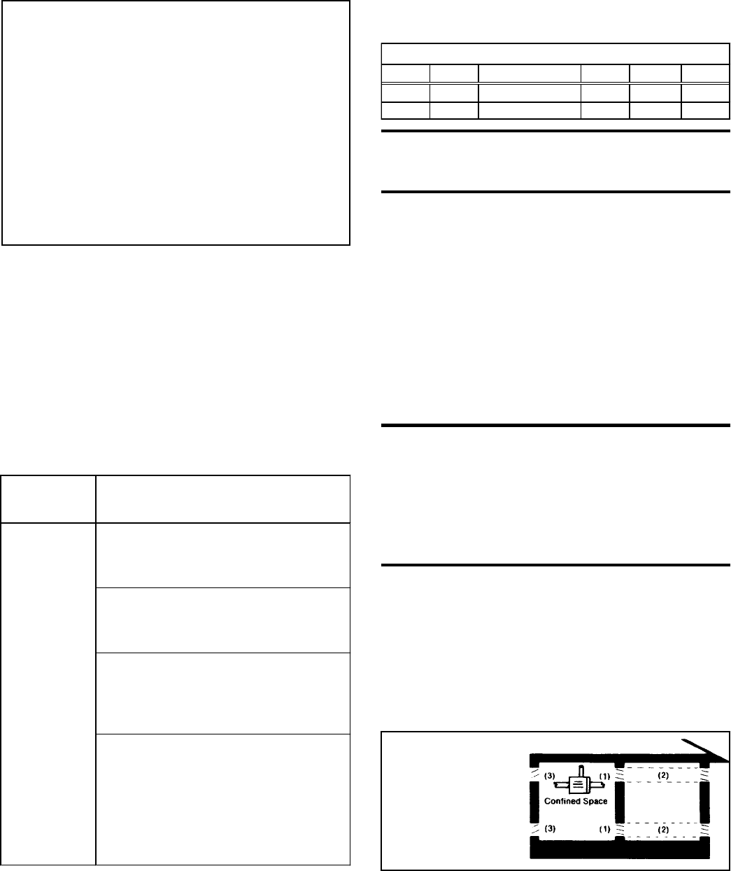
Installation in a Confined Space
Do not install a unit in a confined space without providing wall open-
ings leading to and from the space. Provide openings near the floor
and ceiling for ventilation and air for combustion as shown in Figure
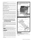
CAUTION: Remove the panel from the bottom rear of the
furnace (See Paragraph 28) and check the burner rack as-
sembly. The burner rack "drawer" should be setting level with
each side on a support rail. Check to assure that EXCES-
SIVE shipping vibration has not caused the burner rack as-
sembly to "drop off" the support rails into the bottom pan. If
the burner rack assembly is positioned properly, close the
back panel. If the burner rack has fallen, remove the screws
holding the burner rack assembly and pull out the burner rack
"drawer". Re-assemble by sliding the burner rack "drawer"
into the heater, being sure that both sides are resting on the
support rails. Re-attach to the support brackets underneath
the burners. Re-insert the burner rack screws and close the
back panel.
Figure 2 -
Confined Space: A
space whose volume
is less than 50 cubic
feet per 1000 BTUH
of the installed
appliance input
rating
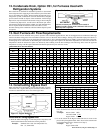
Heating -- Gas Option AG7
Control Option
Amplifier, P/N 48035
Thermostat, P/N 48033
Makeup Air -- Option AG3
Gas Control
Control Switch, P/N 29054
Options
Gasket, P/N 7726
Gasket Retainer Plate, P/N 7727
(All of these Option AG8
options also
Temperature Sensor, P/N 48041
require a
Amplifier, P/N 48037
shipped-
Control Switch, P/N 29054
separate fan Option AG9
control, Opt
Remote Temperature Selector, P/N 48042
CQ1 (P/N
Temperature Sensor, P/N 48041
57960), which
Amplifier, P/N 48035
should be
Control Switch, P/N 29054
at the job Option AG15 or AG16
site.
Remote Temperature Selector, P/N 115848
Stage Adder Module, P/N 115849
Control Switch, P/N 29054
Transformer 115 to 24V, P/N 103055 or
208/230 to 24V, P/N 103497; and 1/2" locknut,
P/N 16222 (for transformer)
Display Module, P/N 115852
(AG16 only)
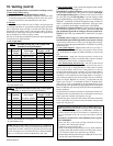
REQUIRED CLEARANCES
Front Top Flue Connector Sides Bottom Rear
6" 6" 6" 6" 12" 29"
152mm 152mm 152mm 152mm 305mm 737mm