


RGM Form 421, Mfg No. 150492, Page 15
16. Combustion Air Proving
Switch
The combustion air proving switch is a pressure sensitive switch
that monitors air pressure to ensure that proper combustion air flow
is available. The switch is a single pole - normally open - device
which closes when a decreasing pressure is sensed in the outlet duct
of the flue gas collection box.
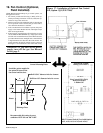
On start-up when the heater is cold, the sensing pressure is at the
most negative level, and as the heater and flue system warm up, the
sensing pressure becomes less negative. After the system has reached
equilibrium (about 20 minutes), the sensing pressure levels off.
If a restriction or excessive flue length or turns cause the sensing
pressure to become less than the switch setpoint, the pressure switch
will function to shut off the main burners. The main burners will
remain off until the system has cooled and/or the flue system resis-
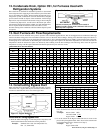
tance is reduced. The Table on the below lists the approximate water
column negative pressure readings and switch setpoints for sea level
operating conditions.
DANGER: Safe operation of this unit requires
proper venting flow. NEVER bypass
combustion air proving switch or attempt to
operate the unit without the venter running and
the proper flow in the vent system. Hazardous
conditions could result. See Hazard Levels,
page 2.
17. Electrical Supply and
Connections
All electrical wiring and connections, including electrical ground-
ing MUST be made in accordance with the National Electric Code
ANSI/NFPA No. 70 (latest edition) or, in Canada, the Canadian Elec-
trical Code, Part I-C.S.A. Standard C22.1. In addition, the installer
should be aware of any local ordinances or gas company require-
ments that might apply.
Check the rating plate on the heater for the supply voltage and cur-
rent requirements. A separate line voltage supply with fused discon-
nect switch should be run directly from the main electrical panel to
the furnace, making connection to leads in the junction box. All
external wiring must be within approved conduit and have a mini-
mum temperature rise of 63
o
F. Conduit from the disconnect switch
must be run so as not to interfere with the service panels of the
furnace.
If the heater has field-installed options that require electrical con-
nections, consult the instruction sheet and wiring diagram supplied
in the option package.
CAUTION: If any of the original wire as
supplied with the appliance must be replaced,
it must be replaced with wiring material having
a temperature rating of at least 105
o
C, except
for sensor lead wires which must be 150
o
C. See
Hazard Levels, page 2.
Specific wiring diagrams that include standard and factory-installed
options are included with the heater. Typical wiring diagrams are
on page 17.
Start-Up Cold Equilibrium Set Point "Off" Set Point "On"
-1.0" w.c. -0.60" w.c. -0.48" w.c. -0.65" w.c.
Operating Sequence
1. Set thermostat at lowest setting
2. Turn on the power to the unit.
3. Turn on main and pilot manual gas valve.
4. Set thermostat at desired setting.
5. Thermostat calls for heat energizing the venter motor.
6. Pressure switch closes, energizing the pilot gas valve and spark gap to
produce a pilot flame on each operating cycle. The sensing probe proves
the presence of pilot flame and energizes the safety switch portion of
the control. The switch action de-energizes the spark gap and ener-
gizes the main gas valve.
7. Fan control (Optional) senses heat exchanger temperature energizing
the fan or blower motor of the air handler.
8. If the pilot flame is extinguished during main burner operation, the
sensing probe detects the absence of the flame and causes the safety
switch to close the main valve. On units with standard intermittent
spark pilot systems, the spark gap recycles. On units with optional
spark ignition with lockout, if the pilot is not established within the
timing cycle (approximately 120 seconds), the unit locks out and must
be reset by interrupting power to the control circuit.
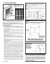
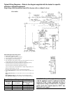
Disconnect Switch
A disconnect switch is a required part of this installation. Switches are
available, as options or parts, or may be purchased locally. When ordered
as an optional component, the disconnect switch is shipped separately.
The disconnect switch may be fusible or non-fusible. When installing, be
careful that the conduit and switch housing are clear of furnace panels
and inspection plates. Allow at least four feet of service room between
the switch and removable panels.
Control Thermostat
A thermostat is not standard equipment but is an installation requirement.
Use either an optional thermostat available with the heater or a field-
supplied thermostat. Install according to the thermostat manufacturer's
instructions.
A 24 volt thermostat must be used to actuate low voltage gas controls. If
line voltage from the thermostat to the unit is desired, consult the factory
representative.
Wiring between the thermostat and the heater must be suitable for a tem-
perature rise of 63
o
F. Labeled thermostat leads are provided in the heater
junction box for connection of thermostat wiring.
Thermostats should be located five feet above the floor on an inside wall,
not in the path of warm or cold air currents, not in corners where air may
be pocketed. Do NOT install on cold air walls. For specific connection
details, refer to instruction packet with the thermostat.
If more than one unit is cycled from one thermostat, separately activated
relays must be substituted at unit thermostat connections.
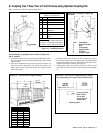
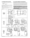
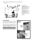
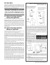
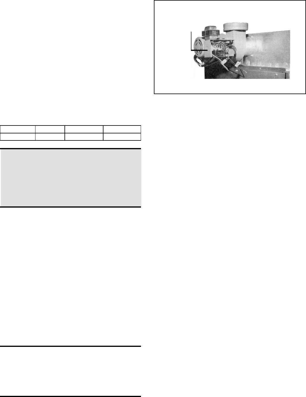
Figure - 15 - Field Wiring Connections
Line Voltage
Connection Tabs
Connect Field
Wiring in the
Electrical Box