


Form 421, Page 18
19. Fan Control (Optional,
Field Installed)
NOTE: Required with makeup air gas control options; see
Paragraphs 22 and 23.
1. Fan control provides the following: a) Delay of fan op-
eration preventing circulation of cold air, and b) Fan op-
eration as long as the unit is hot.
2. The fan control provides additional safety by keeping the
fan in operation in the event that the gas valve fails to
close when the thermostat is satisfied.
3. To be sure that the fan can continue to operate, the power
supply to the heater MUST NOT be interrupted except
when servicing the heater.
4. If the customer wants the heater off at night, the gas valve
circuit SHOULD BE OPENED by a single pole switch
wired in series with the thermostat. Some thermostats are
provided with this feature. Multiple units controlled from
a single thermostat are shut off in the same manner. For
proper operation, be sure fan control wiring is observed.
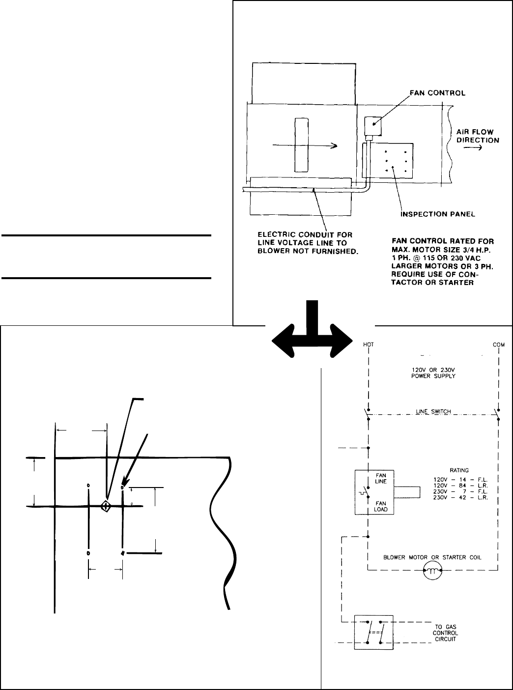
See Figure 17 for installation of fan control and wiring.
WARNING: If you turn off the power
supply, turn off the gas. See Hazard
Levels, page 2.
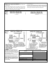
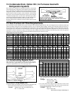
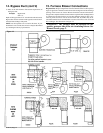
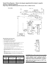
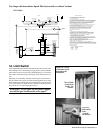
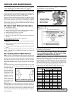
Figure 17 - Installation of Optional Fan Control
Kit, Option CQ1 (P/N 57960)
Location of the Fan
Control Mounting Holes
Typical Fan Control
Wiring (W.D. 145977)
Fan Control P/N 147611,
Honeywell Model
L4064A1347
DP-ST Control Switch (Used with Options
AG3, AG8, AG9, AG15, and AG16)
Drill four 1/8" diameter holes for screws
Drill 13/16" diameter hole for element
3/4"
(19mm)
3"
(76mm)
Recommended dial setting for most
conditions 130
o
F ON and 100
o
F OFF
Install the gasket supplied in
the option kit between the
fan control and the duct.
4"
(102mm)
3"
(76mm)
2-3/8"
(60mm)
Heater
Discharge Duct