


Form 421, Page 10
10. Venting (cont'd)
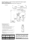
Specific Venting Requirements (read all before installing) (cont'd)
1.
Venter (Flue) Outlet (cont'd)
Venter Outlet Attachment Requirements (cont'd):
o
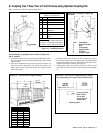
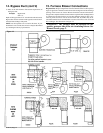
A minimum of 12" of straight pipe is required at the venter outlet
(or transition fitting) before installing an elbow in the vent system.
An elbow should never be attached directly to the venter.
2. Vent Pipe
If installed with a horizontal vent run, use either vent pipe approved
for a Category III heater or appropriately sealed 26-gauge galvanized
steel or equivalent single-wall pipe. If at least half of the equivalent
length of the vent system is vertical, vent pipe approved for a Category
I heater may be used. Single-wall pipe or double-wall (Type B) vent
pipe are suitable for use with a Category I heater.
Use only one of the flue pipe diameters listed in the Vent Length Tables
for the furnace size being installed.
3. Vent Length Tables
4. Vent System Joints - Vent system joints depend on the installa-
tion and the type of pipe being used.
If installed as a Category III heater (required if more than half of
the equivalent length of the vent system is horizontal) and single-
wall vent pipe is being used, use at least two non-corrosive screws
per vent pipe joint and seal all joints to prevent leakage of flue
gases into the building. For sealing joints, the use of Aluminum or
TEFLON
®
(trademark of DuPont Corporation) tape suitable for
550
o
F is recommended (required in California). Vent tape of this
type is available from the heater manufacturer as P/N 98266.
If installed as a Category III heater (required if more than half of
the equivalent length of the vent system is horizontal) and vent
pipe specifically approved for Category III vent systems is be-
ing used, follow the pipe manufacturer's instructions for proper
sealing.
If installed with a Category I vent system (allowed only if at
least half of the equivalent length of the vent system is vertical),
use at least two non-corrosive screws per vent pipe joint on single-
wall pipe or follow the pipe manufacturer's instructions for joining
double-wall pipe.
5.
Vent System Support - Support lateral runs every six feet, us-
ing a non-combustible material such as strap steel or chain. Do not
rely on the heater for support of either horizontal or vertical vent
pipe.
6. Condensation - Single wall vent pipe exposed to cold air or run
through unheated areas must be insulated. Where extreme conditions
are anticipated, install a means of condensate disposal.
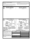
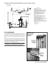
7. Vent Terminal (Pipe and Vent Cap) - The vent system must be
terminated with a suitable vent cap that is the same size as the vent run.
Heaters with an A.G.A. rating plate that are ordered with an optional
vent cap and all heaters with a C.G.A. rating plate have a vent cap
packaged with the heater. If the "standard" size (Vent Length Table 1)
of vent pipe is used, install the vent cap provided. If a vent cap is not
included or if a non-standard size (Vent Length Table 2) of vent pipe is
used, a field-provided cap must be used.
If the vent cap is field-sup-
plied, use a Type L Breidert Air-x-hauster
®
or equivalent vent cap.
(Type L Air-x-hauster
®
is a trademark of The G. C. Breidert Com-
pany.) Use of a vent cap supplied by the pipe manufacturer is not
permitted; the vent cap must be the type approved for use with this
heater. A different style vent cap could cause nuisance problems or
unsafe conditions.
See the illustrations in Figures 9 and 10 for requirements of both verti-
cal and horizontal vent termination. The vent terminal section may be
either single-wall or double-wall (Type B) vent pipe.
If double-wall pipe is used in the vent terminal, follow the instructions
below to attach the vent cap and to connect the double-wall pipe to the
single-wall vent pipe run.
NOTE 1: If the system contains all vertical pipe or a combination
of vertical and horizontal vent pipe, the Maximum Permissible Vent
Length shown in Tables 1 and 2 may be increased one foot for each
foot of vertical pipe, up to a maximum increase of 10 feet for Model
Sizes 75 - 125 and up to 20 feet for Model Sizes 140 - 400.
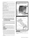
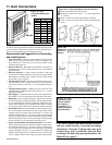
INSTRUCTIONS FOR DOUBLE WALL PIPE INSTALLA-
TION: Material Required: Double wall (Type B) Vent Pipe (Note:
Using only one piece of vent pipe is recommended.); a thimble de-
signed for double wall pipe (if construction is combustible); six
3/4" long sheetmetal screws; the vent cap; and a tube of silicone
sealant
Instructions to attach VENT CAP to DOUBLE WALL (Type B)
VENT TERMINAL
Look for the "flow" arrow on the vent pipe. Attach the vent cap to
the "exhaust" end of the double wall pipe.
1) Slide the vent cap inside the pipe.
2) Drill a hole through the pipe and the vent cap. (Hole should be
slightly smaller than the sheet metal screw being used.) Using a
3/4" long sheet metal screw, attach the cap to the pipe.
3) Repeat Step 2) drilling and inserting two additional screws evenly
spaced (120
°
apart) around the pipe.
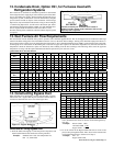
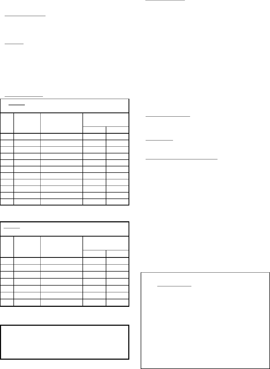
Table 1: Maximum Permissible Vent Lengths with
Standard Vent Pipe Diameters
Vent Pipe Maximum Equivalent Straight
Size Diameter Vent Length Length* - ft (M)
(inches)
(see Note 1 below)
90
O
El bo w 45
O
El bo w
75 4 40 ft (12.2 M) 6 (1.8) 3 (.9)
100 4 50 ft (15.2 M) 7 (2.1) 3.5 (1.1)
125 4 50 ft (15.2 M) 7 (2.1) 3.5 (1.1)
140 4 50 ft (15.2 M) 7 (2.1) 3.5 (1.1)
170 4 50 ft (15.2 M) 7 (2.1) 3.5 (1.1)
200 4 50 ft (15.2 M) 7 (2.1) 3.5 (1.1)
225 5 50 ft (15.2 M) 9 (2.7) 4.5 (1.4)
250 5 50 ft (15.2 M) 9 (2.7) 4.5 (1.4)
300 6 50 ft (15.2 M) 11 (3.4) 5.5 (1.7)
350 6 50 ft (15.2 M) 11 (3.4) 5.5 (1.7)
400 6 50 ft (15.2 M) 11 (3.4) 5.5 (1.7)
*Reduce the maximum vent length by the amount indicated
for each elbow used.
Table 2
: Optional Maximum Permissible Vent Lengths
(Requires an increase in vent pipe diameter.)
Vent Pipe Maximum Equivalent Straight
Size Diameter Vent Length Length* - ft (M)
(inches)
(see Note 1 below)
90
O
El bo w 45
O
El bo w
170 5 60 ft (18.3 M) 9 (2.7) 4.5 (1.4)
200 5 70 ft (21.3 M) 9 (2.7) 4.5 (1.4)
225 6 70 ft (21.3 M) 11 (3.4) 5.5 (1.7)
250 6 70 ft (21.3 M) 12 (3.7) 6 (1.8)
300 7 70 ft (21.3 M) 13 (4.0) 6.5 (2.0)
350 7 80 ft (24.3 M) 13 (4.0) 6.5 (2.0)
400 7 90 ft (27.4 M) 14 (4.3) 7 (2.1)
*Reduce the maximum vent length by the amount indicated
for each elbow used.