


RGM Form 421, Mfg No. 150492, Page 23
All Sizes 75, 100 and 125 (do not have heat exchanger "V" baffles)
and Sizes 140-400 manufactured prior to 11/95 (do not have heat
exchanger "V" baffles) -- Remove the burner rack assembly. Use a
furnace brush (or a piece of heavy wire to which a piece of steel wool
is attached). Brush up and down within the tubes until all soot is re-
moved. With an air hose or brush, clean the outside space between the
lower portions of the heat exchanger tubes to remove any accumulated
dust or light deposits.
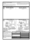
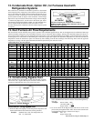
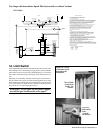
Sizes 140 - 400 manufactured beginning 11/95 (have heat exchanger
"V" baffles) -- Remove the burner rack assembly. Make sure that the
flue pipe is supported. Remove the three screws that attach the venter
housing to the outlet duct (pipe from furnace to venter). The venter
assembly will remain in place. Remove the six screws used to attach
the flue collection box to the top of the furnace. Remove the flue col-
lection box exposing the heat exchanger tubes. The V-shaped tube
baffles can now be removed.
All Sizes -- After cleaning is complete, reverse the procedure to re-
assemble the furnace. Use extreme care so that no unsafe conditions
are created. Check the furnace for proper operation.
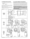
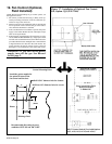
31. Venter
Motor - Remove dirt from the outer surface. The venter motor is per-
manently lubricated; no oiling is required.
Venter Relay - The venter relay controls the venter motor. If relay
contacts fail to "make", the venter motor will not run. If relay contacts
fail to "open, the venter motor will not shut off.
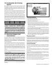
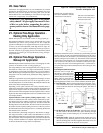
30. Cleaning the Heat Exchanger
CAUTION: When cleaning, wearing eye
protection is recommended.
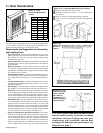
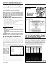
Outer Surfaces (circulating air side) - To clean the outer sur-
faces of the heat exchanger, gain access by removing the inspection
panels in the ductwork or remove the ductwork. Depending on whether
or not the furnace is designed for high CFM (Model prefix "H"), there
may be directional baffles between the heat exchanger tubes. The stan-
dard furnace has baffles between the heat exchanger tubes as shown in
Figure 3B, page 5. (High CFM furnaces have only the top baffle sup-
port which does not need to be removed for cleaning.)
To remove the baffles, remove the screws marked "A" in Figure 3B,
and slide each baffle forward. Use a brush and/or an air hose to remove
accumulated dust and grease deposits from the heat exchanger tubes
and the baffles. Re-install the baffles by sliding them into the rear slot
and replacing the screw. Secure ductwork as necessary.
Inner Surfaces (combustion gas side) - The inner surfaces of the
heat exchanger can be reached for cleaning with the burner rack re-
moved (See Paragraph 28.) An air hose; a long (18 to 24-inch), 1/2"
diameter stiff brush; a flashlight; and a mirror are needed. The required
procedure depends on the size of the furnace and the date of manufac-
ture. Follow these instructions to clean the inner surfaces of the heat
exchanger.
32. Troubleshooting
(Troubleshooting is continued on page 24.)
TROUBLE PRO BABLE CAUS E REMEDY
Venter 1.
No power to unit.
1.
Turn on power, check supply fuses, or circuit breaker.
motor will 2.
No 24 volt power to venter relay.
2.
Turn up thermostat; check control transformer output. Check for loose wire connections.
not start 3.
Venter relay defective.
3.
Replace relay.
4.
Defective motor or capacitor.
4.
Replace motor or capacitor.
Pilot will 1.
Manual valve not open.
1.
Open manual valve.
not light 2.
Air in gas line.
2.
Bleed gas line.
(venter 3.
Dirt in pilot orifice.
3.
Remove and clean with compressed air or solvent (do not ream).
operating) 4.
Gas pressure too high or too low.
4.
Adjust supply pressure. (See Paragraph 9).
5.
Kinked pilot tubing.
5.
Replace tubing.
6.
Pilot valve does not open.
6.
If 24 volt available at valve, replace valve.
7.
No spark:
7.
a)
Loose wire connections
a)
Be certain all wires connections are solid.
b)
Transformer failure.
b)
Be certain 24 volts is available.
c)
Incorrect spark gap.
c)
Maintain spark gap at .100".
d)
Spark cable shorted to ground.
d)
Replace worn or grounded spark cable.
e)
Spark electrode shorted to ground.
e)
Replace pilot if ceramic spark electrode is cracked or grounded.
f)
Drafts affecting pilot.
f)
Make sure all panels are in place and tightly secured to prevent drafts at pilot.
g)
Ignition control not grounded.
g)
Make certain ignition control is grounded to furnace chassis
h)
Faulty ignition controller.
h)
If 24 volt is available to ignition controller and all other causes have been eliminated,
replace ignition control.
8.
Optional lockout device interrupting
8.
Reset lockout by interrupting control at thermostat.
9.
Faulty combustion air proving
9.
Replace combustion air proving switch.
Pilot lights, 1.
Manual valve not open.
1.
Open manual valve.
main valve 2.
Main valve not operating.
2.
will not open a)
Defective valve.
a)
If 24 volt is measured at valve connections and valve remains closed, replace valve.
b)
Loose wire connections.
b)
Check and tighten all wiring connections.