


RGM Form 421, Mfg No. 150492, Page 21
b) No voltage between black and brown leads on the main
gas valve -- check for disconnected or shorted flame sen-
sor lead or flame sensor probe.
When the above conditions are normal and the main gas flow
is still off, the ignition controller is probably defective.
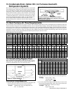
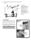
25. Burners and Carryover
System
These duct furnaces have individually formed steel burners
with accurately die-formed ports to give controlled flame
stability without lifting or flashback with either natural or
propane gas. The burners are lightweight and factory mounted
in an assembly which permits them to be removed as a unit
for inspection or service.
All burners are equipped with two flash carryover systems
that receive a supply of gas simultaneously with the main
burner. During regular service, check the main burner ports,
the carryover assemblies, and the orifices for cleanliness.
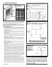
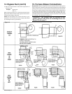
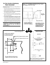
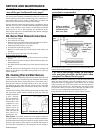
26. Burner Air Adjustment
Burner air shutters are not normally required on natural gas furnaces. Air shut-
ters are supplied on propane gas units and may require adjustment.
Before making any adjustments to the air shutters, allow the heater to operate for
about fifteen minutes with the air shutters open. The slotted screw on the end
manifold bracket moves the air shutters and adjusts all burners simultaneously.
Turning the screw clockwise opens the shutters; counterclockwise closes the
shutters. After the furnace has been in operation for 15 minutes, close the air
shutters observing the flame for yellow-tipping. Open the shutters until the yel-
low disappears. A limited amount of yellow-tipping is permissible for propane
gas. Other fuels should not display any yellow-tipping.
When making the adjustment, close the air shutters no more than is necessary to
eliminate the problem condition.
DANGER: Failure to install and/or adjust air shutters
according to directions could cause property damage,
personal injury, and or death.
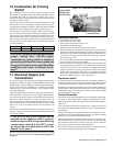
27. Check Installation and Start-Up
DANGER: The gas burner in this gas-fired equipment is designed and equipped to provide safe and
economically controlled complete combustion. However, if the installation does not permit the burner
to receive the proper supply of combustion air, complete combustion may not occur. The result is
incomplete combustion which produces carbon monoxide, a poisonous gas that can cause death. Safe
operation of indirect-fired gas burning equipment requires a properly operating vent system which
vents all flue products to the outside atmosphere. FAILURE TO PROVIDE PROPER VENTING
WILL RESULT IN A HEALTH HAZARD WHICH COULD CAUSE SERIOUS PERSONAL INJURY
OR DEATH.
Always comply with the combustion air requirements in the installation codes and in Paragraph 5.
Combustion air at the burner should be regulated only by manufacturer-provided equipment. NEVER
RESTRICT OR OTHERWISE ALTER THE SUPPLY OF COMBUSTION AIR TO ANY HEATER.
Indoor units installed in a confined space must be supplied with air for combustion as required by
Code and in Paragraph 5 of this heater installation manual. MAINTAIN THE VENT SYSTEM IN
STRUCTURALLY SOUND AND PROPERLY OPERATING CONDITION.
Start-Up
oTurn electric and gas supply on to the furnace. Adjust the thermo-
stat or ductstat so that a call for heat exists. Observe for complete
sequencing of safety pilot and ignition.
Check installation after start-up:
oWith the unit in operation, measure manifold gas pressure. Mani-
fold pressure for natural gas should be 3.5" w.c. and 10" w.c. for
propane gas. See Paragraph 9.
oTurn the unit off and on, pausing two minutes between each cycle.
Observe for smooth ignition. On two-stage or modulating burner
systems, manipulate temperature adjustment slowly up and down to
see if control is sequencing or modulating properly. Raising tem-
perature setting drives burner on or to full fire.
oObserve burner flame at full fire. Natural gas flame should be about
1-1/2" in height with blue coloring. Propane gas flame should be
approximately the same length with blue coloring. Yellow tipping
may appear on propane gas. If yellow extends beyond 1/2 to 3/4",
adjust air shutters. See Paragraph 26 .
oChecked the limit control. With the heater on, completely block off
distribution air. The limit control should open within a few minutes,
shutting off the gas supply to the main burners.
oPlace "Owner's Envelope" containing Limited Warranty Card, this
booklet, and any optional information in an accessible location near
the heater. Follow the instructions on the envelope.
Check the installation prior to start-up:
oCheck suspension. Unit must be secure and level.
oBe certain the electrical supply matches voltage rating of the fur-
nace. (Refer to the rating plate.)
oCheck all field wiring against the wiring diagram. Be sure wire
gauges are as required for the electrical load. Verify that fuses or
circuit breakers are in place and sized correctly.
oCheck clearances from combustibles. Requirements are shown in
Paragraph 5.
oIf installed in a confined space, verify that the furnace has adequate
combustion air supply. See Paragraph 5.
oCheck vent system to be sure that it is installed according to the
instructions in Paragraph 10. Be sure to have used an approved
vent terminal.
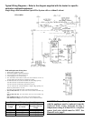
oCheck piping for leaks and proper gas line pressure. Bleed gas
lines of trapped air. See Paragraph 9.
a) Turn manual shutoff valve to off position.
b) Turn gas supply on.
c) Observe gas meter for movement, or
d) Attach pressure gauge readable to .1" w.c. and after turning gas on
for ten seconds, turn gas supply off. No change in pressure should
occur over a three-minute period.
e) If either c) or d) above indicate a leak, locate leak by brushing a
leak-detecting solution on all fittings. Bubbles will appear at a leak.
Repair and repeat tests.