


RGM Form 421, Mfg No. 150492, Page 11
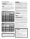
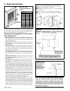
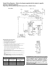
Figure 9 -
Vertical
Vent
Terminal
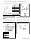
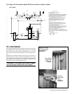
Horizontal Vent Terminal Clearances
The location of the termination of the hori-
zontal vent system must be in accordance with
National Fuel Gas Code Z223.1. See table for
required minimum clearances.
If the vent terminal is to be installed near
ground level, position it at least six inches
above maximum anticipated snow depth.
NOTE: Maintain the required clearance
from the wall to the vent terminal cap for
stability under wind conditions and to pro-
tect the building.
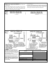
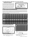
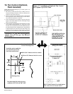
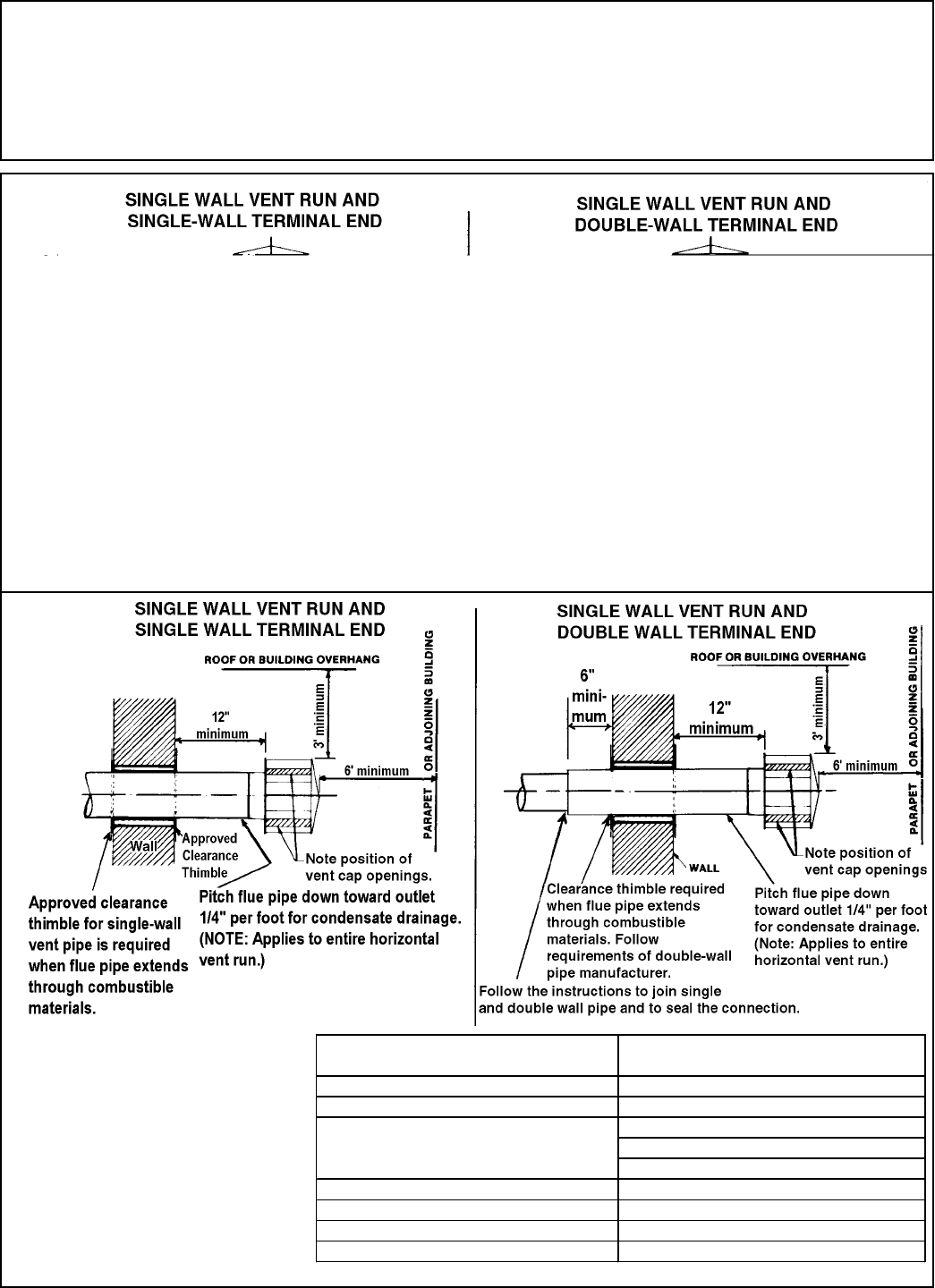
Figure 10 -
Horizontal
Vent
Terminal
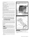
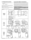
Instructions to connect the SINGLE WALL VENT system to a
DOUBLE WALL (Type B) VENT TERMINAL:
1) Slide the single wall pipe inside the inner wall of the double-wall
terminal pipe.
2) Drill a hole through both walls of the double wall pipe and the
single wall pipe. (Hole should be slightly smaller than the sheet
metal screws being used .) Using a 3/4" long sheet metal screw,
attach the two pieces of pipe. Do not overtighten.
3) Repeat Step 2) drilling and inserting two additional screws evenly
spaced (120
°
apart).
4) To seal the annular opening (the gap between the single and double
wall pipe), run a large bead of silicone sealant in the opening. The
bead of sealant must be large enough to seal the opening, but it is
not necessary to fill the full volume of the annular area.
Structure
Minimum Clearances for Vent Termination
Location (all directions unless specified)
Forced air inlet within 10 ft (3.1m) 3 ft (0.9m) above
Combustion air inlet of another appliance 6 ft (1.8m)
4 ft (1.2m) horizontally
4 ft (1.2m) below
3 ft (0.9m) above
Electric meter, gas meter * and relief equipment 4 ft (1.2m) horizontally
Gas regulator * 3 ft (0.9m)
Adjoining building or parapet 6 ft (1.8m)
Grade (ground level) 7 ft (2.1m) above
*Do not terminate the vent directly above a gas meter or service regulator.
Door, window or gravity air inlet (any building
opening)