


RGM Form 421, Mfg No. 150492, Page 13
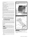
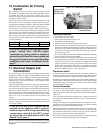
12. Condensate Drain, Option CS1, for Furnaces Used with
Refrigeration Systems
These furnaces are certified for installation upstream or downstream
from refrigerated units supplying air below the dew point of the ambi-
ent air surrounding the furnace. When installed downstream from a
refrigeration system, condensation will form and therefore, adequate
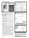
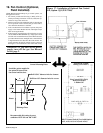
provision must be made to dispose of the condensate. A drain flange,
Option CS1, may be installed on the furnace casing as shown in Figure
13. When using Option CS1, seal all holes in the bottom pan. Termi-
nate the drain outside of the building. NOTE: A 4-inch minimum clear-
ance is required under the furnace if a 90
o
street elbow is used.
Periodic cleaning of the condensate collection and the disposal system
is required.
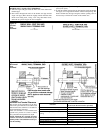
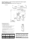
Figure 13 - Condensate Drain, Option CS1 (P/N 31765)
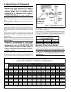
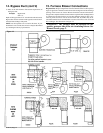
The duct furnace must be installed on the positive pressure side of the field supplied blower. The air throughput must be within the CFM range
stated on the heater rating plate. The air distribution must be even over the entire heat exchanger. Turning vanes should be employed in elbows or
turns in the air inlet to ensure proper air distribution (See Paragraph 15). If it is determined that the blower CFM is greater than allowed or desirable,
see Paragraph 14 for instructions on determining the correct size of bypass duct required. To determine temperature rise, the inlet and outlet air
temperatures should be measured at points not affected by heat radiating from the heat exchanger. The following charts show the approved
temperature rise range with the required CFM and the internal pressure drop for each size of unit.
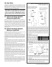
13. Duct Furnace Air Flow Requirements
Seal holes in bottom pan. Terminate drain outside of
building. Periodic cleaning of the condensate collector and
disposal system is required.
Model EEDU (80% thermal efficient)
Size
Temperature
Rise
CFM P.D. CFM P.D. CFM P.D. CFM P.D. CFM P.D. CFM P.D. CFM P.D. CFM P.D. CFM P.D. CFM P.D. CFM P.D.
50°F
1105 0.24 1475 0.43 1840 0.49 2065 0.65 2505 0.67 2945 0.67 3315 0.69 3685 0.67 4420 0.70 5160 0.75 5895 0.77
60°F
920 0.16 1225 0.30 1535 0.33 1720 0.43 2085 0.46 2455 0.46 2765 0.47 3070 0.45 3685 0.47 4300 0.52 4915 0.52
70°F
790 0.10 1050 0.21 1315 0.25 1475 0.32 1790 0.33 2105 0.35 2370 0.36 2630 0.34 3160 0.35 3685 0.38 4210 0.38
80°F
695 0.07 920 0.16 1150 0.20 1290 0.24 1565 0.25 1840 0.26 2070 0.27 2300 0.26 2765 0.27 3225 0.28 3685 0.28
90°F
615 0.05 815 0.12 1020 0.17 1145 0.20 1390 0.19 1635 0.20 1840 0.21 2045 0.20 2455 0.22 2565 0.23 3275 0.22
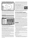
Model HEEDU (80% thermal efficient, high CFM)
Size
Temperature
Rise
CFM P.D. CFM P.D. CFM P.D. CFM P.D. CFM P.D. CFM P.D. CFM P.D. CFM P.D. CFM P.D. CFM P.D. CFM P.D.
20°F
2765 0.60 3685 1.09 4605 1.14 5160 1.50 6265 1.64 7370 1.64 8295 1.69 9215 1.67 11060 1.64 12900 1.64 14745 1.64
30°F
1840 0.28 2455 0.50 3070 0.52 3440 0.66 4175 0.73 4915 0.73 5530 0.75 6140 0.72 7370 0.73 8600 0.73 9830 0.73
40°F
1380 0.16 1840 0.28 2300 0.27 2580 0.36 3130 0.38 3685 0.39 4145 0.40 4605 0.40 5530 0.39 6450 0.40 7370 0.38
50°F
1105 0.12 1475 0.18 1840 0.18 2065 0.22 2505 0.24 2945 0.24 3315 0.26 3685 0.24 4420 0.24 5160 0.25 5895 0.24
60°F
920 0.10 1225 0.13 1535 0.14 1720 0.17 2085 0.17 2455 0.17 2765 0.18 3070 0.17 3685 0.17 4300 0.18 4915 0.17
65°F
850 0.08 1130 0.11 1415 0.12 1585 0.15 1925 0.14 2265 0.14 2552 0.15 2835 0.14 3400 0.14 3970 0.15 4535 0.15
70°F
-- -- -- -- -- -- -- -- 1790 0.12 2105 0.12 2370 0.13 2630 0.11 3160 0.12 3685 0.13 4210 0.13
250 300 350 400
300 350 400
75 100 125 140 170 200 225
170 200 225 25075 100 125 140
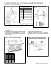
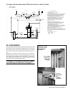
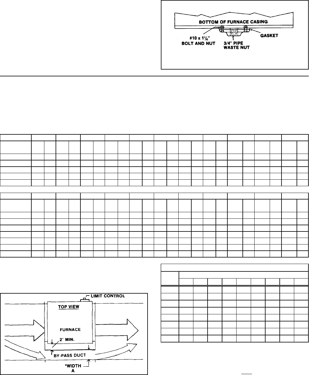
14. Constructing Bypass Duct
When the CFM of air throughput is greater than desirable or permis-
sible for the unit, a bypass duct may be constructed. Follow these in-
structions to determine the correct size of the bypass duct.
Bypass CFM
"A" Pressure Drop through the Furnace
Width 0.10 0.15 0.20 0.25 0.30 0.35 0.40 0.45 0.50
3"
490 530 610 700 780 830 900 960 1010
4"
630 750 870 980 1090 1160 1250 1310 1400
5"
850 1010 1190 1300 1410 1520 1640 1730 1810
6"
1050 1290 1480 1650 1800 1940 2090 2200 2320
7"
1250 1510 1760 1960 2180 2320 2500 2650 2800
8"
1490 1810 2100 2350 2560 2760 2940 3110 3290
9"
1700 2100 2400 2700 2970 3200 3400 3600 3800
10"
1920 2350 2760 3090 3650 4020 4300 4550 4800
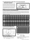
Directions for Sizing Bypass Duct
1) From the tables in Paragraph 13, find the pressure drop (P.D.) and
the allowable CFM for the furnace that is being installed.
Example: Standard Size 170 @ 70
o
F temperature rise;
P.D. .33; CFM 1790
Figure 13 - Bypass Duct
2) Subtract the allowable CFM from the actual CFM of the installa-
tion to determine how much air must be diverted through the by-
pass duct.
Example: Blower CFM 3000
Allowable CFM -1790
Bypass CFM 1210
3) Go to the column in the Bypass CFM Chart that is closest to the
pressure drop through the heater. Move down in that column until
you find the CFM closest to the answer in Step 2).
Example: P.D. .35
Bypass CFM 1520