


7/50D Plus or 7/50D Controller Chapter 3: Installation 28
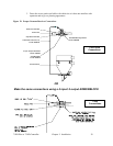
Connecting Vacuum Receivers to the Network
Make sure that all previous installation steps have been done first before starting this task.
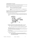
To connect a vacuum receiver to the network:
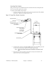
1. Attach one connector of the yellow patch cord to the terminal on the vacuum receiver
terminal box. Tighten the cord grip ring until snug.
2. Attach the other connector to the upper left terminal of the ArmorBlock. Tighten the
cord grip ring until snug.
Note: Retain the terminal caps from the ArmorBlock. They may be used
later.
*** The installation steps listed above also apply to the 7/50D 4-connector
ArmorBlock.
Note the following illustrations for 4 and 8-connector ArmorBlocks:
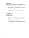
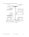
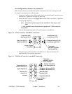
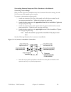
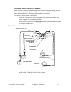
Figure 10: 7/50D 4-Connector ArmorBlock Connections
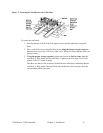
3. Dress the excess patch cord cable with cable ties so it does not interfere with
operation and gives a pleasing appearance.
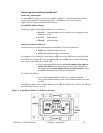
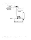
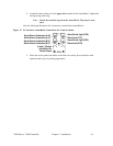
Figure 11: 7/50D Plus 8-Connector ArmorBlock Connections
Not used
Bypass Switch (B-I2)
Demand Switch (A-I0)
Volume Fill Prox. (A-I1)
Receiver Level
Sensor (C-I4)
Purge Solenoid (H-O6)
8 Input / 8 Output
ArmorBlock
RPV Material 'A' Solenoid (F-O2)
RPV Material 'B' Solenoid (F-O3)
Local Alarm Light (E-O1)
Sequence Valve (E-O0)
Slide Gate (G-O4)
Blowback (G-O5)
T-Connector
AB#1485P-P1R4-DR4
Part No. A0555169
Pump Fault #1 (B-I2)
Pump Fault #2 (B-I3)
Pump Verify (A-I0)
High Vacuum (A-I1)
4 Input / 4 Output
ArmorBlock
Blowback Solenoid (D-O2)
Local Alarm Light (D-O3)
Pump Starter (C-O0)
Vent Solenoid (C-O1)
T-Connector
AB#1485P-P1R4-DR4
Part No. A0555169