


7/50D Plus or 7/50D Controller Chapter 3: Installation 14
Chapter 3: Installation
3-1 Uncrating
7-Pump, 50D & D Plus-Station Controllers are shipped mounted on a skid, enclosed in a
plastic wrapper, and contained in a cardboard box.
1. Pry the crating away from the skid.
Note: Remove the nails holding the box to the skid and lift the box off
carefully; avoiding staples in the 1’ x 4’ wood supports. Cut the steel
banding.
2. Use a pry bar to remove the blocks securing the unit to the skid.
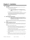
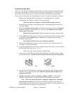
3. Lift unit from sides, inserting forklift under the base. The forks must be equidistant
from the centerline of the unit and the unit must be balanced on the forks. Lift
slowly and only high enough to clear the skid. Use a pry bar if necessary to
carefully remove the skid from the unit.
4. Lower slowly.
3-2 Mounting the Control Panel
Note: Before you mount the panel, consider how you run wiring to the
KwikLink connectors, ArmorBlocks, vacuum hoppers, the filter cham-
ber atmospheric valve (if so equipped) and the pump motor starter(s),
vacuum switch(es), and vent valve(s).
Mount the control panel on a flat, vertical area. It should be a visible area that gives your
operator access to the control. The panel requires a low voltage power drop as listed on the
serial tag.
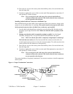
3-3 System Installation Overview
Installing the 7-pump 50-station controller is easy and straightforward. Because the system
uses networked distributed I/O modules, you’ll only need to run two cables for the entire
system.
The following is a typical installation sequence:
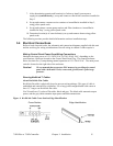
1. Run the black power and the grey data KwikLink™ flat cables from the start of the
system to the end, attaching them to vacuum tubing with nylon cable ties.
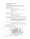
2. Set up mounting plates with tubing clamps; install KwikLink™ connectors and
ArmorBlocks onto mounting plates as required.
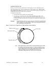
3. Install KwikLink connectors and ArmorBlock™ cable plates to mounting plates, and
install on vacuum tubing at each node location, just before a T-fitting or valve.
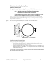
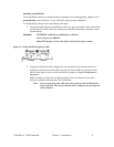
4. Install cable terminations.
5. Determine location of network system nodes, and set addresses for ArmorBlocks as
required.
6. Set up and connect to the controller and, if purchased, remote display. Connect grey
patch cords from controller terminals to KwikLink connectors installed in Step 3.