


7/50D Plus or 7/50D Controller Chapter 3: Installation 15
7. After determining quantity and location(s) of where to install system power
supply(ies) (consult factory); set up and connect to KwikLink connectors installed in
Step 3.
8. Set up and connect vacuum receiver stations to ArmorBlocks installed in Step 3,
using yellow patch cords.
9. Set up and connect vacuum pump stations and filter chambers to ArmorBlocks
installed in Step 3, using yellow patch cords.
10. Determine location(s) of central alarm(s); set up and connect alarms using yellow
patch cords.
The following sections provide detailed information on these installation steps.
3-4 Electrical Connections
Refer to local electrical codes, the schematic and connection diagrams supplied with this unit
and the serial tag for wiring considerations. Run all wiring in conduit if codes require it.
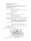
Making Control Panel Power Drop Wiring Connections
Hardwire the input power at 115/1/50-60 VAC or 230/1/50-60 VAC, depending on the
specifications, which are located on the Control Panel Serial Tag. The control enclosure
draws less than five (5) amps during normal operation at 115/1/50-60 VAC. The main power
switch is located on the right side of the enclosure.
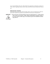
Caution! We recommend that you protect PLC memory by providing the control
panel with a dedicated circuit, a true earth ground, and a spike/surge
protector.
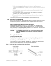
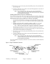
Running KwikLink™ Cables
About KwikLink Flat Cables
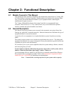
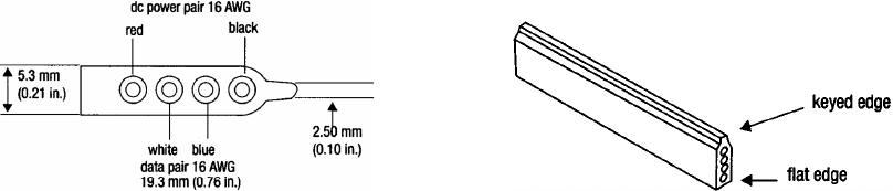
KwikLink flat cable is physically keyed to prevent wiring mishaps. This type of cable is
unshielded and contains four conductors. Use a long-jawed straight-bladed cable cutter at
least 1½” long to cut KwikLink flat cable.
You’ll install two (2) colors of flat cable: black and grey. The black cable transmits output
power, and the grey cable transmits input power and data transmission.
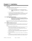
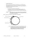
Figure 1: KwikLink Cable Cross-Section, Edge Identification
Cross Section Edge Identification