


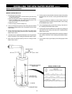
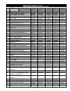

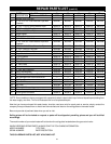

33
PERIODIC MAINTENANCE
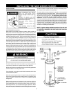
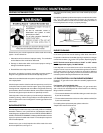
VENTING SYSTEM INSPECTION
At least once a year a visual inspection should be made of the venting
system. You should look for:
1. Obstructions which could cause improper venting. The combustion
and ventilation air flow must not be obstructed.
2. Damage or deterioration which could cause improper venting or
leakage of combustion products.
3. Rusted flakes around top of water heater.
Be sure the vent piping is properly connected to prevent escape of
dangerous flue gasses which could cause deadly asphyxiation.
Obstructions and deteriorated vent systems may present serious health
risk or asphyxiation.
Chemical vapor corrosion of the flue and vent system may occur if air for
combustion contains certain chemical vapors. Spray can propellants,
cleaning solvents, refrigerator and air conditioner refrigerants, swimming
pool chemicals, calcium and sodium chloride, waxes, bleach and process
chemicals are typical compounds which are potentially corrosive.
If after inspection of the vent system you found sooting or deterioration,
something is wrong. Call the local gas utility to correct the problem and
clean or replace the flue and venting before resuming operation of the
water heater.
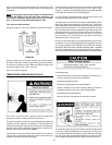
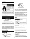
BURNER INSPECTION
Flood damage to a water heater may not be readily visible or immediately
detectable. However, over a period of time a flooded water heater will
create dangerous conditions which can cause DEATH, SERIOUS BODILY
INJURY, OR PROPERTY DAMAGE. Contact a qualified installer or service
agency to replace a flooded water heater. Do not attempt to repair the
unit! It must be replaced!
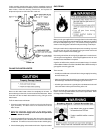
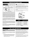
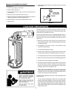
At least once a year a visual inspection should be made of the main
burner and pilot burner, see Figure 111.
You should check for sooting. Soot is not normal and will impair proper
combustion.
Soot build-up indicates a problem that requires correction before further
use. Turn “OFF” gas to water heater and leave off until repairs are
made, because failure to correct the cause of the sooting can result in a
fire causing death, serious injury, or property damage.
FIGURE 111.
BURNER CLEANING
In the event your burner needs cleaning, follow these instructions:
If inspection of the burner shows that cleaning is required, turn the gas
control knob clockwise (
) to the “OFF” position, depressing slightly.
NOTE: The knob cannot be turned from “PILOT” to “OFF” unless
knob is depressed slightly. DO NOT FORCE.
Loose deposits on or around the burner can be removed by carefully
using the hose of a vacuum cleaner inserted through the access doors
of the water heater. If the burner needs to be removed for additional
cleaning, call the local gas utility to remove and clean the burner and
correct the problem that required the burner to be cleaned.
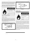
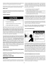
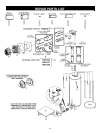
L.P. GAS CONTROL VALVE & BURNER ASSEMBLY
Propane (L.P.) gas control valve and burner assembly replacement in-
formation.
For Propane (L.P.) Gas Models Only:
Your water heater is equipped with a Propane (L.P.) gas control valve
and a main burner assembly with left hand threads for the following
fittings and their connections.
• The connection between the manifold and the gas control valve (A to
B) are left hand threads.
• The connection between the main burner orifice and the manifold (C to
D) are left hand threads.
For ordering these replacement parts, please refer to the
“Repair Parts” section of this manual.
FIGURE 112.