


16
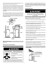
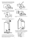
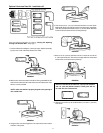
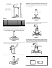
14. Install the vent collar assembly through the wall, connecting it to the
extension and/or elbow depending on which one was used.
FIGURE 45.
15. Four wood screws are supplied to temporarily attach the collar to the
exterior wall of the building. However, other types of screws may
have to be substituted depending on the construction material of the
exterior wall.
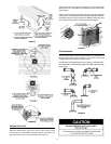
FIGURE46.
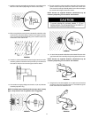
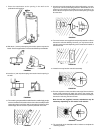
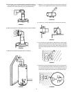
16. Insert the 3” (76 mm) diameter flue extension pipe into the vent collar
assembly (flared and notched end first) and rotate clockwise to lock
the studs to the slots in the extension pipe.
FIGURE 47.
17. Connect the vent cap by sliding it’s end over the 3” (7.6 cm) diam-
eter extension pipe an O-ring.
NOTE: to facilitate ease of assembly of the vent cap to the 3”
(7.6 cm) pipe a soap solution can be applied to the O-ring
gasket.
FIGURE 48.
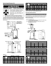
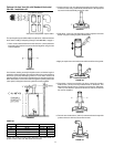
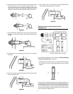
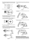
18. The vent cap has four holes around the outer edge. Remove the four
screws used to temporarily attach the collar to the exterior wall. Then
secure the vent cap to the exterior wall using the same four screws.
NOTE: Screws are supplied. However, substitution may be
necessary depending on the exterior wall material.
FIGURE 49.
19. Go back indoors to attach inside collar to the inside wall. Place the collar
against the wall. Secure to wall by using four long sheet metal screws.
NOTE: Screws are supplied. However, substitution may be
necessary depending on the exterior wall material.
FIGURE 50.
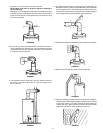
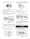
20. Using the tube of sealant supplied, apply an ample amount of sealant
around the edge of the vent pipe where it is inserted through the
inside collar. This will seal air draft from the walls.
FIGURE 51.