


11
ALL INSTALLATIONS
For ease of assembly the installation of the various kit combinations
has been broken into individual sections. The two steps below are
common to all installations. Once these have been performed, you
need only to refer to the type installation that pertains to you.
Installation Using Vent Kits:
1. Standard Vent Kit 9000687 ............................................. Page 11
2. Optional Vertical Vent Kit................................................. Page 14
with Standard Vent Kit
3. Optional Horizontal Vent Kit ............................................. Page 17
4. Optional Horizontal.......................................................... Page 19
and Vertical Vent Kits
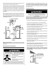
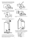
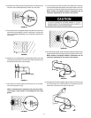
Cutting The Opening Through The Outside Wall
After thoroughly reading the “Locating the New Water Heater”
section of this manual and you have chosen a suitable water
heater installation site, use Chart #1 to determine dimensions for
the wall opening.
Cut a 6 1/4” (159 mm) diameter hole completely through the outside
wall.
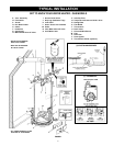
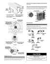
FIGURE 14.
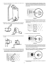
Water Heater Attitude
There is a certain amount of variance with regard to the direction the
water heater faces.
Standing in front of the water heater (gas control facing you), set the
3” (76 mm) diameter elbow (slotted end) on the flue. This will give you
a better understanding of the relation of the vent assembly to the
opening in the wall and more importantly any possibility of interference
of venting and water piping.
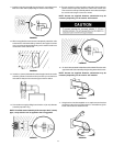
The direction of the water heater can now be made. Also consider the
gas control valve to insure installation, lighting and maintenance
accessibility are retained.
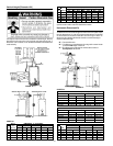
NOTE: Supplementary installation instructions are applicable only if
this direct vent water heater is provided with the alternate brown
porcelain-enameled vent cap and the 6” (152 mm) vent wall assembly
show below, See pages 22 thru 24.
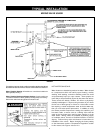
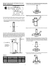
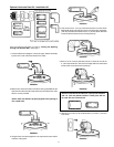
Standard Vent Kit - Installation #1
The opening through the wall should be cut at this time. If this has not
been done, refer to “Cutting The Opening Through The Outside Wall ”
section.
1. Lock the elbow to the straight 3” (76 mm) flue pipe. Set this assembly
in place on the end of the water heater’s flue collar.
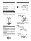
FIGURE 15.
2. Mark the flue collar at the slots in the elbow. Using a #22 drill bit, drill
holes into the flue collar at the two slots and secure the elbow to the
flue collar using the screws provided.
NOTE: Make sure elbow is properly aligned to opening in the
outside wall.
FIGURE 16 .
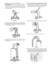
3. Using the tube of sealant supplied, run an ample amount around the
oval flare of the jacket.
FIGURE 17.