


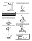
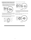

20
FIGURE 72.
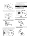
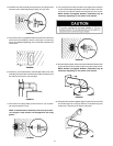
CHART #4.
*GAL CAP *BTU’s in 1000’s - NAT./L.P. A
40 36/36 48 3/4” 124 cm
50 38/38 57 1/2” 146 cm
40 40/40 48 3/4” 124 cm
50 48/44 61” 155 cm
75 55 NAT. 63” 160 cm
*Check the model and rating plate attached to the water heater for
specific model number and other detailed information.
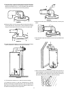
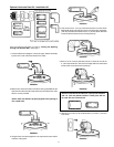
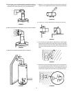
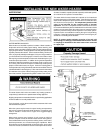
2. Set the vertical 3” (7.6 cm) diameter telescoping flue section in place on
the flue collar. Using a #22 drill bit, drill two holes (180° apart) and secure
the vertical assembly to the flue collar with the two supplied screws.
FIGURE 73.
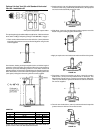
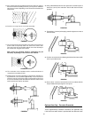
3. Slide the 6” (15.2 cm) vent telescoping section apart to reveal the
beads. Fill the beads using the supplied caulking.
FIGURE 74.
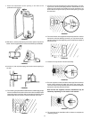
4. Apply an ample amount of sealant around the oval flare of the jacket.
FIGURE 75.
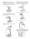
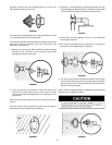
5. Place the 6” (15.2 cm) vent section over the 3” (7.6 cm) flue section.
Subtract 3/4” (1.9 cm) from the predetermined “X” dimension. This
determines the length of the 6” (15.2 cm) vent extension. Slide the 6”
(15.2 cm) vent extension apart to this dimension and secure with the
two screws supplied.
FIGURE 76.
6. Form the round end of the 6” (15.2 cm) vent extension to the top of the
jacket and secure with four sheet metal screws.
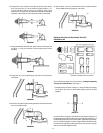
FIGURE 77.
7. Place the 3” (7.6 cm) elbow on the flue extension. Align the elbow to
the hole previously made in the outside wall. Using the slots in the
elbow, mark the 3” (7.6 cm) diameter end of the flue extension. Using
a #22 drill bit, drill two holes into the flue extension and secure with
the two provided sheet metal screws.
FIGURE 78.
NOTE: the standard kit includes a 3” (7.6 cm) flue extension
and a 6” (15.2 cm) elbow extension. These parts will not
be used with the horizontal kit.