


18
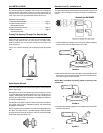
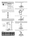
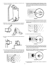
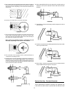
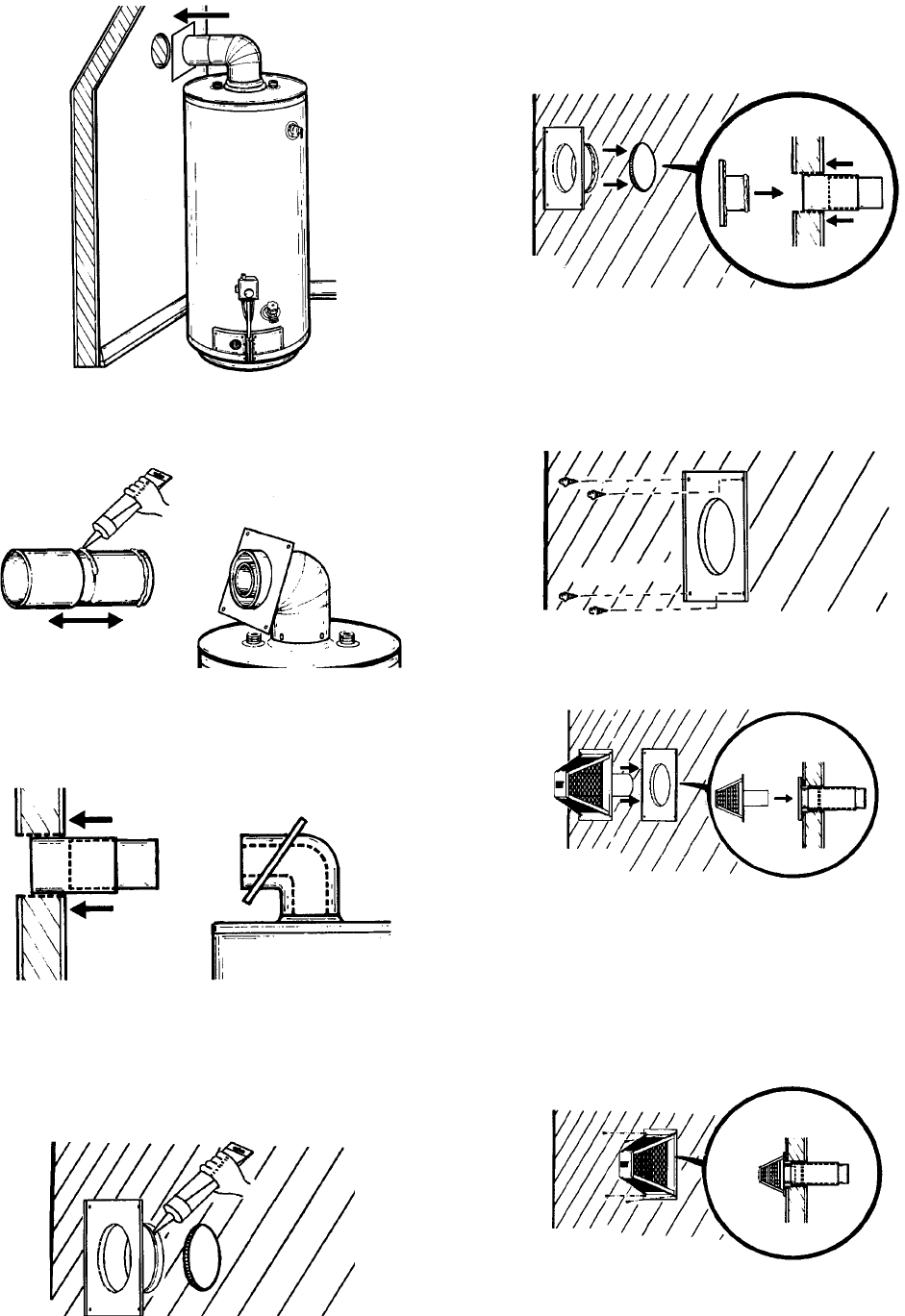
7. Place the waterheater at the opening in the wall at the
predetermined clearance.
FIGURE 58.
8. Slide the 6” (152 mm) telescoping vent section apart to expose the
beads. Use the supplied tube of sealant and fill the exposed beads.
FIGURE 59.
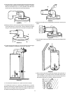
9. Insert the 6” (152 mm) telescoping vent section into the opening in
the wall.
FIGURE 60.
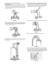
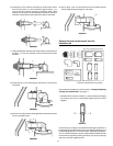
10. The remaining vent parts will be installed from the outside. Apply ample
amount of sealant to the inside surface of the collar assembly that will
contact the exterior wall. Also, apply sealant to the bead around the
outside edge at the end of the 6” (152 mm) diameter vent collar.
FIGURE 61.
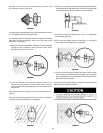
11. Insert the vent collar assembly through the wall opening, connect-
ing to the 6” (152 mm) telescoping extension. Remember, the vent
extension has not been connected so it may be necessary to go
back outdoors and push it back up into the wall opening for a tight
fit to the collar.
FIGURE 62.
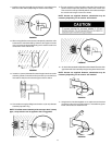
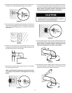
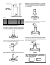
12. Four wood screws were supplied to temporarily attach the collar to
the exterior wall of the building. However, you may have to substi-
tute other types of screws depending on the construction material of
the exterior wall.
FIGURE 63.
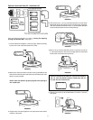
13. Insert the vent cap into the vent collar assembly.
FIGURE 64.
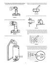
14. The vent cap has four holes around the outer edge. Remove the four
screws used to temporarily attach the collar to the exterior wall.
Then secure the vent cap assembly with the vent collar assembly to
the exterior wall using the same screws.
Note: Screws are supplied; however, substitution may be
necessary depending on the exterior wall material.
FIGURE 65.
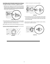
15. The remainder of the installation will be indoors to complete the
assembly process.