


22
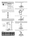
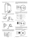
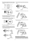
15. Four wood screws were supplied to temporarily attach the collar to
the exterior wall of the building. However, you may have to substitute
other types of screws depending on the construction material of the
exterior wall.
FIGURE 86.
16. Insert the vent cap into the vent collar assembly.
FIGURE 87.
17. The vent cap has four holes around the outer edge. Remove the four
screws used to temporarily attach the collar to the exterior wall.
Then secure the vent cap assembly with the vent collar assembly to
the exterior wall using the same screws.
Note: Screws are supplied; however, substitution may be
necessary depending on the exterior wall material.
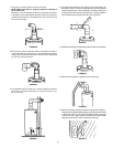
FIGURE 88.
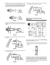
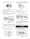
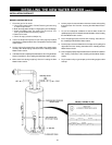
18. The remainder of the installation will be conducted indoors to
complete the assembly process.
19. Collapse the 6” extension assembly as shown below. Install the O-
ring end of the 3” (7.6 cm) extension approximately 1 1/4” (3.2 cm) into the
end of the vent cap. If necessary, apply a soap solution to the O-ring
to ease the assembly. Rotate the extension clockwise until the other
end is locked to the studs on the elbow.
FIGURE 89.
20. Using a #22 drill bit, drill holes 180° apart at the connection point of
the two 3” (76 mm) flue extensions. Secure with the two screws
provided.
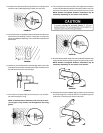
FIGURE 90.
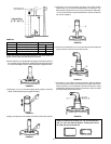
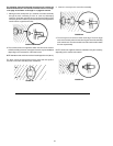
21. Expand the 6” (152 mm) telescoping extension pipes to connect at
the vent elbow.
FIGURE 91.
22. Push the vent collar from the elbow against the wall and secure with
the four provided screws.
FIGURE 92.
23. Secure the 6” (152 mm) vent extension to the vent elbow with the
two provided screws spacing them 180° apart.
FIGURE 93.
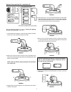
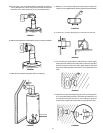
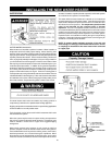
Optional Vent Cap - Porcelain-Enameled
These supplementary installation instructions are applicable only
if this direct vent water heater is provided with the alternate brown