


23
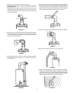
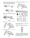
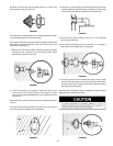
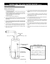
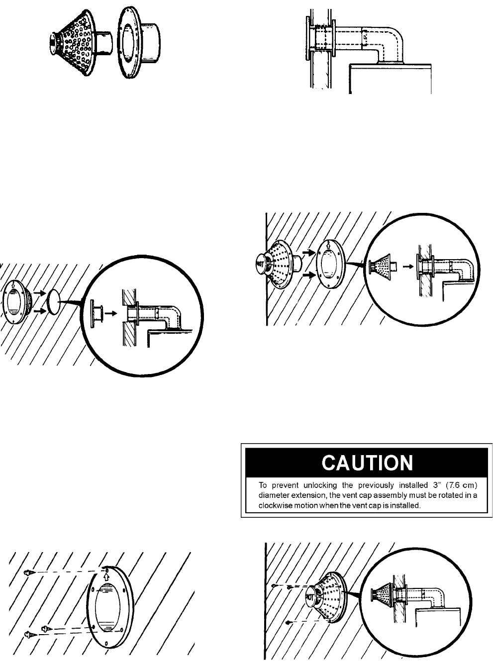
porcelain-enameled vent cap assembly and the 6” (15.2 cm) vent
wall assembly shown by Figure 94.
FIGURE 94.
The water heater model designation on the rating plate will have a suffix
“P” to indicate this alternate vent cap assembly.
The alternate installation instructions below will replace the itemized
instructions in the manual as follows: Items 11 thru 15 on page 13 and
items 14 thru 18 on page 16.
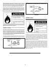
1. Making sure the arrow points “UP”, install the vent collar assembly
through the wall, connecting it to the extension and/or elbow
depending on which one was used.
FIGURE 95.
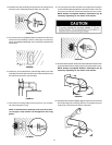
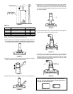
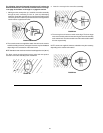
2. Three wood screws are supplied to attach the collar to the
exterior wall of the building. However, other types of screws
may have to be substituted depending on the construction of the
exterior wall.
NOTE: alternate screws used must not have a head larger than 3/8”
(.95 cm).
The three screws must be placed at every other hole (120° apart) to
secure the vent collar assembly to the outside wall.
FIGURE 96.
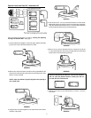
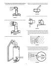
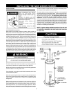
16. Insert the 3” (7.6 cm) diameter flue extension pipe into the vent collar
assembly (flared and notched end first). Lock the flue extension pipe
to the flue elbow by rotating clockwise to lock studs to slots.
FIGURE 97.
4. Connect the vent cap by sliding it over the 3” (7.6 cm) diameter
extension pipe and O-ring.
NOTE: for ease of assembly of the vent cap to the 3” (7.6 cm) pipe a
soap solution can be applied to the O-ring gasket.
FIGURE 98.
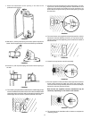
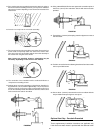
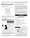
5. The vent cap has six holes around the outer edge. The three larger
ones are to fit over the three screws securing the vent collar assem-
bly to the exterior wall. The three smaller ones will now be used to
attach the vent cap assembly.
NOTE: screws are supplied. However, substitution may be necessary
depending on the exterior wall material.
FIGURE 99.