


19
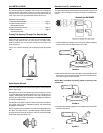
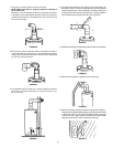
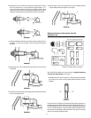
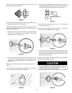
16. Collapse the 6” flue extension assembly as shown below. Install
the O-ring end of the 3” (7.6 cm) extension approximately 1 1/4”
(3.2 cm) into the end of the vent cap. If necessary, apply a soap
solution to the O-ring to ease the assembly. Rotate the 3” extension
clockwise until the other end is locked to the studs on the elbow.
FIGURE 66.
17. Using a # 22 drill bit, drill holes 180° apart at the connection point of
the two 3” (7.6 cm) flue extensions. Secure with the two screws
provided.
FIGURE 67.
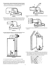
18. Expand the 6” (15.2 cm) telescoping extension to connect at the
vent elbow.
FIGURE 68.
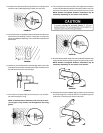
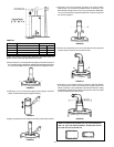
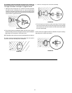
19. Push the vent collar from the elbow against the wall and secure with
the four provided screws.
FIGURE 69.
20. Secure the 6” (15.2 cm) vent extension to the vent elbow with the
two provided screws spacing them 180° apart.
FIGURE 70.
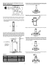
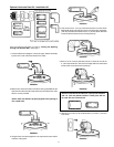
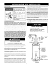
Optional Vertical and Horizontal Vent Kit -
Installation #4
If the vent hole has not been cut, refer to section, “Cutting The Opening
Through The Outside Wall.” See page 11.
1. First determine how far the vertical 3” (7.6 cm) diameter telescoping
flue sections are to be set and locked together with two screws
supplied.
FIGURE 71.
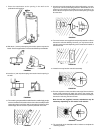
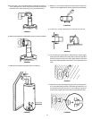
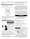
Use the Chart #4, and figure 72 to determine the length of expansion of
the telescoping flue sections. Because of manufacturing tolerances, put
the telescoping extension on the water heater, adjust the height (dimen-
sion “X”) and mark the point. Once the length has been determined, lock
the two sections together by drilling two holes (180° apart) in the pipe
and secure with the supplied screws.