


15
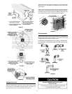
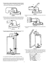
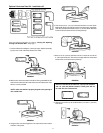
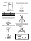
7. Place the 3” (76 mm) elbow on the flue extension.
NOTE: Make sure elbow is properly aligned to opening in
the outside wall.
Mark the 3” (76 mm) diameter end of the flue extension at the slots
in the elbow. Using a #22 drill bit, drill holes into the flue extension
at the two slots and secure the elbow to the flue extension using
the screws provided.
FIGURE 38.
8. Be sure the 6” (152 mm) diameter elbow is centered around the 3”
(76 mm) diameter flue. Secure the 6” (152 mm) diameter vent pipe
using two sheet metal screws at the cnnection of the elbow and
6” (152 mm) vertical extension.
FIGURE 39.
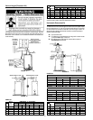
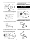
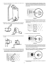
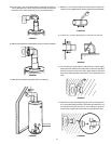
9. The standard vent kit includes a 6” (152 mm) diameter extension
pipe which is used when dimension “E” (refer to Chart 2) is over
6 1/2” (165 mm).
FIGURE 40.
10. If “E” dimension is less than 6 1/2” (165 mm) move to next step. If “E”
dimension is over 6 1/2” (165 mm), assemble the 6” (152 mm) diameter
extension pipe to the 6” (152 mm) diameter vent elbow and secure
using two sheet metal screws. Using the tube of sealant supplied,
run an ample amount around the joint to insure a good seal.
FIGURE 41.
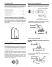
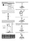
11. Slide the vent collar (to be installed later) over the 6” (152 mm) vent elbow.
FIGURE 42.
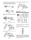
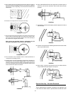
12. Move the water heater into position at the vent opening.
FIGURE43.
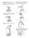
13. Take the remaining vent parts outside to complete the installation.
Using the tube of sealant supplied, apply an ample amount of sealant
to the inside surface of the collar assembly that will contact the
exterior wall. Also, apply sealant to the bead around the outside
edge at the end of the 6” (152 mm) diameter vent collar.
FIGURE 44.