


100
9
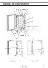
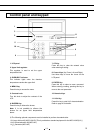
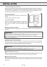
1. Outer door: The outer door is held to the frame with a magnetic seal. A door heater is installed in the
door panel. The door opening is reversible. Contact a Sanyo representative or agent to change the door
hinge from left to right or vice versa.
2. Inner door: The inner door is made of tempered glass. However do not subject the glass to excessive
impacts.
3. Leveling feet: The leveling feet can be turned to adjust the height. Adjust the feet so that the Incubator
is level.
4. Trays: The trays can be pulled forward.
5. Tray supports: The tray supports can be removed by lifting the front side and pulling toward you.
6. Side supports: The right and left side supports can be removed for disinfection. Refer to page 36 and
37.
7. Fan cover: The fan cover serves as the inlet for circulating air. It is removable.
8. Duct: The duct for the path for circulating air. It is removable.
9. Fan (inside the duct): The fan is made from polypropylene resin. It can be disinfected in an autoclave.
10. Sample air outlet: The sample air outlet also functions as an internal gas outlet. Normally, cover this
outlet with the sample air outlet cap.
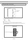
11. Connecting port A/B for CO
2
gas pipe: When the optional MCO-21GC Automatic CO
2
Cylinder
Changeover System is installed, both ports A and B are available. If the MCO-21GC is not installed, only
port A is available. Refer to page 14 for gas cylinder connection. Ensure that the gas pressure is set at
0.03 MPaG (0.3 kgf/cm
2
G, 4.3 psiG). Refer to page 57 for automatic CO
2
cylinder changeover system.
12. Door switch: The door switch detects when the door is open and stops the circulating fan and
electromagnetic valve for CO
2
and UV lamp.*
13. Humidifying pan: Fill the humidifying pan with sterile distilled water. Install the pan properly so that it
can be covered with the pan cover.
14. Humidifying pan cover: The cover prevents UV light entering the chamber. When filling the pan, lift
the front side and take out the pan. Refer to page 39 for details.
15. UV lamp*: This Sanyo UV lamp does not generate ozone. Never look directly at the UV light. For
replacement, contact a Sanyo representative or agent.
16. Water level sensor for humidifying pan: This sensor detects the water level in the humidifying pan.
Refer to page 35 for details.
17. Remote alarm terminals: Refer to page 11.
18. Access port: Place the silicon caps on the port both outside and inside when the port is not being
used.
19. Power switch: This is the main switch for the Incubator. It also functions as an overcurrent breaker.
20. Glow starter*: The glow started if for the UV lamp (model FG-7P)
21. Attachment location for electric key: This is the attachment location for the electric key included in
the optional Component H
2
O
2
Decontamination Kit (MCO-HL). This kit must be attached to perform H
2
O
2
decontamination. Refer to the installation procedure for MCO-HL for details.
22. Sample air outlet cap: Always attach this cap except when using the sample air outlet.
* MCO-19AIC(UV) or when an optional UV System Kit (MCO-19UVS) is installed.