


17
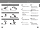
SPEED DOME CAMERA
16
SPEED DOME CAMERA
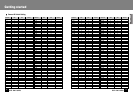
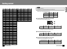
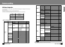
Camera ID SW2 SW1 Remarks
ID = 192 C 0
ID = 193 C 1
ID = 194 C 2
ID = 195 C 3
ID = 196 C 4
ID = 197 C 5
ID = 198 C 6
ID = 199 C 7
ID = 200 C 8
ID = 201 C 9
ID = 202 C A
ID = 203 C B
ID = 204 C C
ID = 205 C D
ID = 206 C E
ID = 207 C F
ID = 208 D 0
ID = 209 D 1
ID = 210 D 2
ID = 211 D 3
ID = 212 D 4
ID = 213 D 5
ID = 214 D 6
ID = 215 D 7
ID = 216 D 8
ID = 217 D 9
ID = 218 D A
ID = 219 D B
ID = 220 D C
ID = 221 D D
ID = 222 D E
ID = 223 D F
ID = 224 E 0
ID = 225 E 1
ID = 226 E 2
ID = 227 E 3
ID = 228 E 4
ID = 229 E 5
ID = 230 E 6
ID = 231 E 7
ID = 232 E 8
ID = 233 E 9
ID = 234 E A
ID = 235 E B
ID = 236 E C
ID = 237 E D
ID = 238 E E
ID = 239 E F
Camera ID SW2 SW1 Remarks
ID = 240 F 0
ID = 241 F 1
ID = 242 F 2
ID = 243 F 3
ID = 244 F 4
ID = 245 F 5
ID = 246 F 6
ID = 247 F 7
ID = 248 F 8
ID = 249 F 9
ID = 250 F A
ID = 251 F B
ID = 252 F C
ID = 253 F D
ID = 254 F E
ID = 255 F F
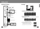
·Factory Default : Camera ID = 1
The rotary switch is on the controller board (controllable from the initial PAN position)
Note
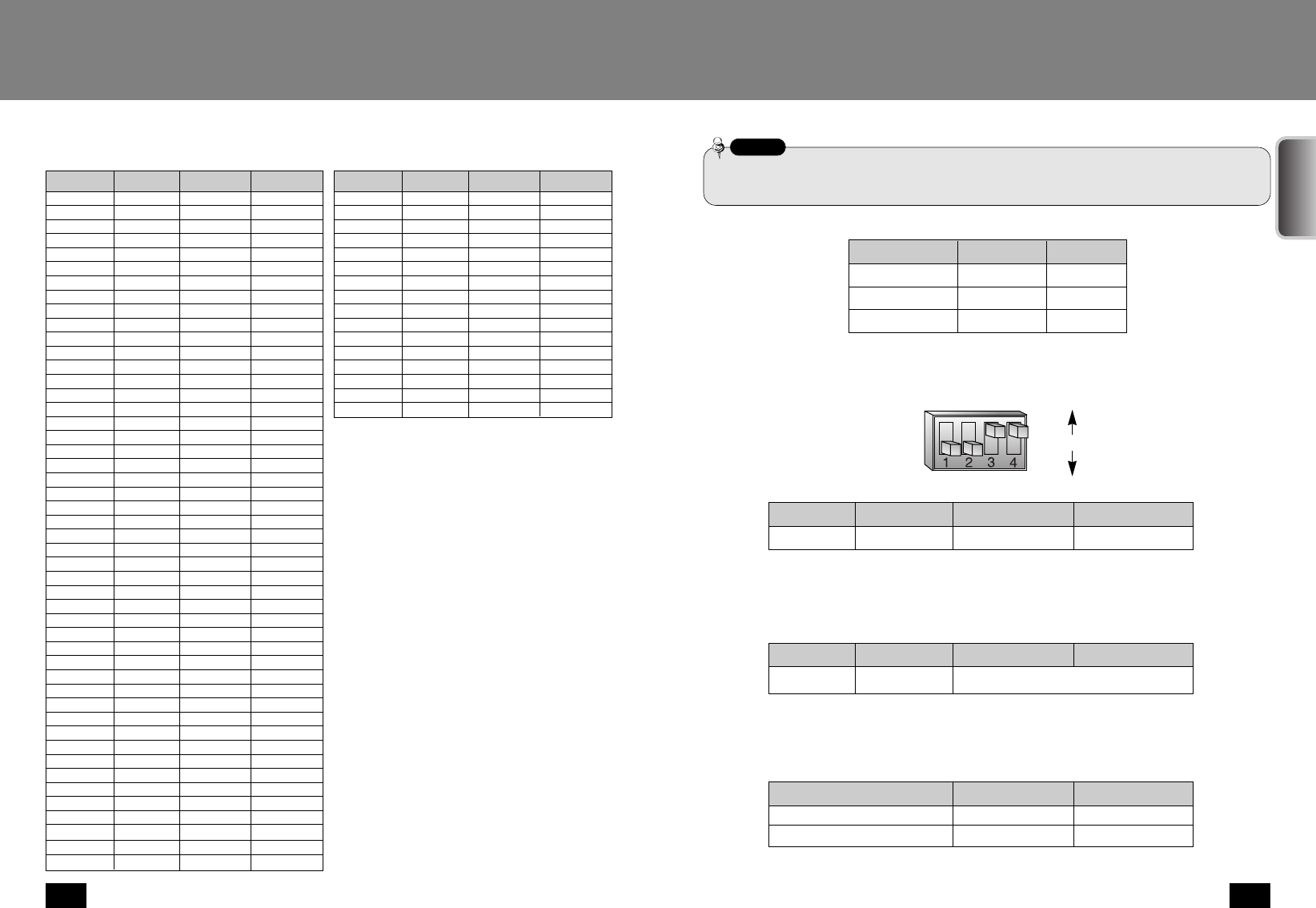
·The three kinds of camera ID below cannot be used.
Camera ID
ID = 0
ID = 160
ID = 175
0
A
A
0
0
F
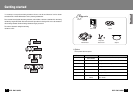
R-SW2 R-SW1
●
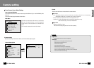
Controller Model Setting (Mainframe front panel)
·Set the controller model by switching Dip Switch No. 1
●
Factory Default (Mainframe front panel)
SW3
ON
OFF
Functions
Controller Setting
SVR-430/900 /1620/1630
SCC-16, SCC-3000
SW3-#1
ON
OFF
Note) Factory Default : OFF
Note) Factory Default : OFF
Simultaneous control by a controller and a DVR is not allowed.
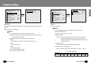
Note) Factory Default: On for both switches
Camera Connection Position
Longest Route Terminal
On the route
ON
OFF
ON
OFF
SW3-#3 SW3-#4
Functions
Factory Default
OFF for both switches
SW3-#2
ON
OFF
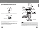
Getting started
●
RS-485 Terminal Setting (Mainframe front panel)
·Set the terminal by switching Dip Switch No. 3 and 4 On/Off.
ENGLISH