


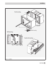

Connecting the sensors
Cables with a minimum cross-section of 2 x 0.5 mm² can be connected to the terminals at the
back panel of the housing.
Connecting the actuators
Connect cables with at least 1.5 mm² suitable for damp locations to the terminals of the control
-
ler output. The direction of travel needs to be checked at start-up.
4
Set mode switch to (+). Valves must open.
4
Set slide switch to (–). Valves must close.
Connecting the pumps
Connect all cables with at least 1.5 mm² to the terminals of the controller as illustrated in the corre
-
sponding connection diagram (–> page 92 to 96).
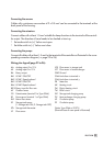
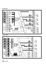
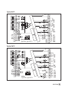
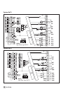
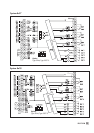
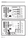
Wiring plan legend (page 92 to 96):
AA Analog output 0 to 10 V VFS Flow sensor in storage tank
AE Analog input 0 to 10 V VFT Flow sensor in heat exchanger
BA Binary output GND Ground
BA1 UP HK1 ON/OFF GWxLimit alarm to terminal x
BA2 UP HK1 Speed reduced GWyLimit alarm to terminal y
BA3 UP HK2 ON/OFF ZB Meter bus
BA4 UP HK2 Speed reduced HK Heating circuit
BE/V Binary input for flow rate FW District heating circuit
AF Outdoor sensor TW DHW circuit
FG Potentiometer (terminal 3 at Type 5244) SLP Storage tank charging pump
RF Room sensor (terminal 1 at Type 5244) TLP Heat exchanger charging pump
RüF Return flow sensor UP Circulation pump
SF Storage tank sensor
(1: Storage tank ON; 2: Storage tank OFF)
ZP Circulation pump
STh Storage tank thermostat
Option Type 5244 or 5257-5
(Terminal base of room panel is illustrated)
VF Flow sensor
EB 5179 EN 91