


4
Room sensor RF: Upon failure of the room sensor, the controller functions according to the
settings for operation without a room sensor. For example, optimized operation is switched
over to reduced operation. Adaptation operation is interrupted. The last determined heating
characteristic is not changed anymore.
4
Storage tank sensors SF1 and SF2: Upon failure of one of these sensors, the storage tank is
not charged anymore.
Sensor breakage status
In InF7 and InF8 levels, it is possible to see which sensor does not function properly. The status of
the sensors is shown over function blocks together with the string
bruch
. A function block is as
-
signed to each sensor and is set when the sensor data input is incorrect after one minute.
4
InF7 (only with Co7 -> Fb05 = ON): Error status display of the recognized LON controller
and its sensor breakage status, for example
7403b = TROVIS 5174 Controller, sensor breakage bit 03
7919b = TROVIS 5179 Controller, sensor breakage bit 19
The relationship between the set bit and the associated sensor can be found in the Mounting
and Operating Instructions (EB) of the recognized LON controller.
4
InF8: Sensor breakage status display of the sensor belonging to the controller. The set bits
remain visible in the case of failure for at least one minute ( appears on the right-hand side
of the set bit number, see page 69).
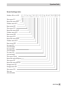
When an SMS text message alarm or fax alarm is issued (see sections 8.6 and 8.7)
Fuehl
ap-
pears on the display next to the status of the connected sensors. One “o” appears for every
working sensor and one “F” for every defective sensor. The sequence is the same as the set bits
on page 69.
4
Example: “Fuehl:oFoFFooooooooooooooooo” = Defective resistor inputs 1, 3 and 4 (return
flow sensor RüF1, room sensor RF1 and flow sensor VF1)
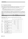
8.2 Collective error alarm
Should an error occur in the controller, it can be indicated over binary output BA4.
BA4 is activated when the error status register does not equal 0. BA4 is a DC voltage output in
an open collector circuit and may only be loaded with 24 V/10 mA at the maximum. If the Col
-
lective error alarm function is active, BA4 is no longer available for pump management.
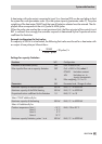
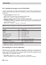
Function
WE Configuration
Potentiometer in pre-control circuit OFF Co5 -> Fb16 = ON
68 EB 5179 EN
Operational faults