


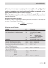
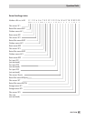
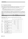
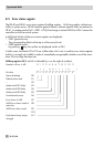

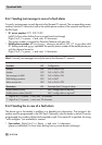
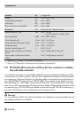

Example of a transfer to the control system:
The error status register is transferred as a word <w> in a holding register (HR) whose value is
calculated as follows:
<w> = ([D0] x <1> + [D1] x <2> ) +...+ ([D11] x <2048>)
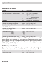
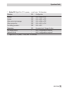
Holding register 61 (A set bit is indicated by on the right of number):
Number = Bit no. in HR 0 123456789101112131415
Bit value 2
0
2
1
2
2
2
3
2
4
2
5
2
6
2
7
2
8
2
9
2
10
2
11
2
12
2
13
2
14
2
15
Thermal disinfection D0
Limit at terminal x active D1
Limit at terminal y active D2
VFmax at DHW exchanger D3
Temperature monitoring D4
–D5
–D6
–D7
Extended
limit monitoring
(D8 to D15)
D8
D9
D10
D11
D12
D13
D14
D15
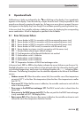
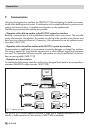
8.6 Error alarms
Error alarms can be sent over a modem either directly to the control station or over the SMS text
message function to a mobile phone or to a fax. Just one function (Modbus, SMS function or fax
function) can be selected at one time since the functions use the same interface. The error alarms
to a mobile phone and to a fax contain the number of the affected error status register (FSR1),
the fault as per error status register (BitNo), the controller ID and the bit number (Bit xx).
EB 5179 EN 73
Operational faults