


1.3 Display
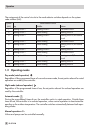
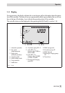
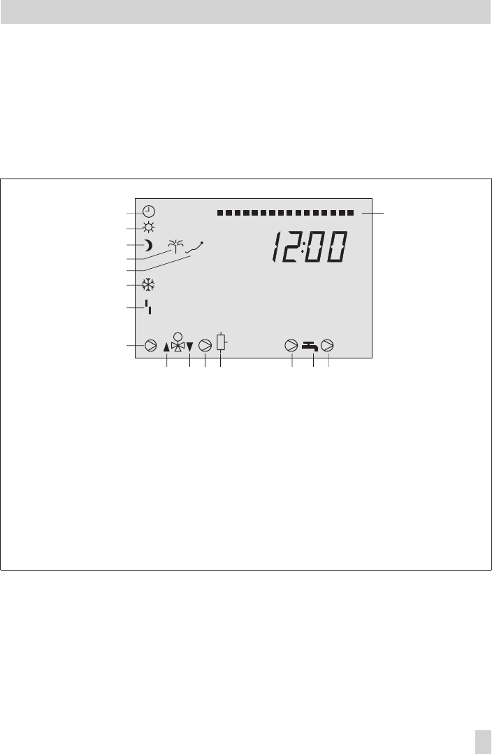
During operation, the display indicates the current time as well as information about the opera
-
tion of the controller. The times-of-use are represented by black squares below the row of num
-
bers at the top of the display. Icons indicate the operating status of the controller.
The controller status can be displayed in the operating level (InF level) (–> section 1.4).
EB 5179 EN 9
Operation
10 11 12 13 14 15 16 17 18 19123456789 0212223240
1
1
452
1
2
3
4
5
6
7
8
9
10 11 12 1413 15
Fig. 1 · Icons
1 Automatic operation
2 Day mode
(rated operation)
3 Night mode
(reduced operation)
4 Vacation mode
5 Public holiday mode
6 Frost protection
7 Malfunction
8 Circulation pump RK1–3
9 Valve RK1–3 or
Primary valve: OPEN or
DHW: OPEN
10 Valve RK1–3 or
Primary valve: CLOSED
or DHW: CLOSED
11 Storage tank charging
pump SLP
12 DHW storage tank
13 Circulation pump ZP
14 DHW demand
15 Exchanger charging pump
TLP
16 Time-of-use
16