


8 Operational faults
Malfunctions or faults are indicated by the icon blinking on the display.
Error
immediately
appears on the display. Press the enter key to open the error level. It may be possible to view
several error alarms by pressing the enter key. As long as an error alarm is present, the error
level appears in the display loop, even though it has not been opened by pressing the enter key.
In the error level, the controller indicates a defective sensor by displaying the corresponding
sensor combination. A fault is displayed as specified in the list below.
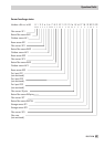
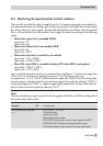
8.1 Error list/sensor failure
4
ERR 1 Sensor broken in RK1 (in connection with the corresponding sensor icon)
4
ERR 2 Sensor broken in RK2 (in connection with the corresponding sensor icon)
4
ERR 3 Sensor broken in RK3 (in connection with the corresponding sensor icon)
4
ERR 4 Sensor broken in DHW circuit (in connection with the sensor icon)
4
ERR 5 Sensor broken in primary circuit (in connection with the sensor icon)
4
ERR -1 Standard data entered again (default settings)
4
ERR -2 Final temperature of the thermal disinfection not reached
4
ERR -3 Mode selector switch 1 defective
4
ERR -4 Mode selector switch 2 defective
4
ERR -5 Mode selector switch 3 defective
4
ERR 10 Temperature limitation of DHW heat exchanger active
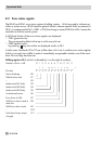
In the error level,
ERR1
to
ERR5
on the display indicates the sensor failures as per the error list.
Detailed information over a sensor failure can be retrieved within the information level by poll-
ing individual temperatures: each sensor icon displayed together with––––indicates a defec
-
tive sensor. The following list explains how the controller responds to the failure of the different
sensors.
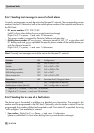
4
Outdoor sensors AF: When the outdoor sensor fails, the controller uses a flow temperature
set point of 50 °C or the
Max. flow temperature
(when the
Max. flow temperature
is smaller
than 50 °C).
4
Flow sensor VF: When the flow sensor is defective, the controller continues to work with the
valve in the last position.
4
Flow sensor in the DHW heat exchanger VFT: The DHW control valve is closed when the
sensor fails.
4
Flow sensor in the DHW storage tank VFS: The flow set point for the DHW heat exchanger
is only controlled with VFT. The display blinks.
4
Return sensor RüF: When the return flow sensor is defective, the controller continues to work
without the return flow temperature limitation function.
EB 5179 EN 67
Operational faults