


6 Functions of the DHW circuit
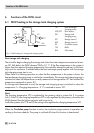
6.1 DHW heating in the storage tank charging system
Start storage tank charging
The controller begins charging the storage tank when the water temperature measured at sen-
sor SF1 falls below the
DHW demand ON
by 0.1 °C. If the flow temperature in the system is
higher than the required charging temperature, the controller attempts to reduce it in the heat-
ing circuit for maximum 3 minutes before the heat exchanger pump together with the storage
tank charging pump start to run.
When there is no heating operation or when the flow temperature in the system is lower, the
heat exchanger charging pump is switched on immediately. The storage tank charging pump is
switched on when the temperature currently measured at storage sensor VFT has reached the
temperature measured at sensor SF1.
If a storage tank thermostat is used, the storage tank charging pump is switched on when the
temperature T =
Charging temperature
– 5 °C is reached at sensor VFT.
Note!
The charging temperature VFT is regulated by the primary valve in system Anl 2. In systems
Anl 4, 5 and 10, the charging temperature VFT is only regulated by the primary valve when the
DHW demand has the highest set point and has priority.
In all other systems (Anl 7, 8 and 9) the mixing valve regulates the charging temperature VFT.
When the Circulation pump function is active, the circulation pump remains in operation ac
-
cording to the time schedule. The pump is switched off when this function is deactivated.
52 EB 5179 EN
Functions of the DHW circuit
TW
SF1
SF2
VFS
VFT
SLP
TLP
ZP
KW
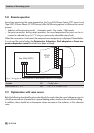
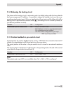
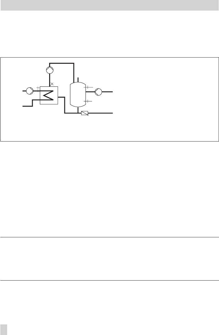
Fig. 5 · DHW heating in a storage tank charging system
TLP Heat exchanger
charging pump
VFS/VFT Flow sensors
SLP Storage tank
charging pump
SF1 Storage sensor 1
SF2 Storage sensor 2
ZP Circulation pump
TW DHW
KW Cold water