


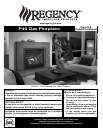

Regency
®
P40 Direct Vent Gas Fireplace
8
INSTALLATION
INSTALLATION
This includes:
1) Clocking the appliance to ensure the correct
fi ring rate (rate noted on label 45,000 (NG)
Btu/h, 43,000 (LP) Btu/h) after burning
appliance for 15 minutes.
2) If required, adjusting the primary air to ensure
that the fl ame does not carbon. First allow
the unit to burn for 15-20 min. to stabilize.
CAUTION: Any alteration to the product that
causes sooting or carboning that results
in damage is not the responsibility of the
manufacturer.
MANUFACTURED
MOBILE HOME
ADDITIONAL
REQUIREMENTS
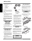
1) Ensure that structural members are not cut
or weakened during installation.
2) Ensure proper grounding using the #8
ground lug provided. See "Wiring Diagram"
section.
LOCATING YOUR
GAS FIREPLACE
1) When selecting a location for your fi replace,
ensure that the clearances are met.
2) The appliance must be installed on a fl at,
solid, continuous surface (e.g. wood, metal,
concrete). This may be the fl oor, or raised up
on a platform to enhance its visual impact.
The appliance must be installed on a metal
or wood panel extending the full width and
depth of the appliance.
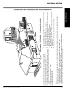
3) The P40 Direct Vent Gas Fireplace can be
installed in a recessed position or framed
out into the room as in A, B, C, D. See
Diagram 1.
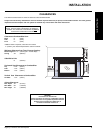
HEARTH
REQUIREMENTS
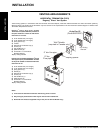
A 40" (1016mm) wide x 16" (406mm) deep x
1-1/2" (38mm) thick hearth is required, unless
the unit is raised 4" (102mm).
4) This appliance is Listed for bedroom
installations when used with the FireWizard
(millivolt thermostat system). Some areas
may have further requirements, check local
codes before installation.
5) The P40 Direct Vent Gas Fireplace is
approved for alcove installations, see
"Clearances" section for details.
6) We recommend that you plan your installation
on paper using exact measurements for
clearances and fl oor protection before
actually installing this appliance. Have an
authorized inspector, dealer, or installer
review your plans before installation.
Note: For vent terminations see "Exterior
Vent Termination Locations"
section.
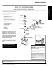
HEATWAVE
DUCT KIT
The HeatWave Air Duct Kit increases the
effectiveness of your fi replace by dispersing
warm air from the fi replace to remote locations in
the same room or other rooms in your home.
Up to two kits may be installed on the fi replace.
Please Note: Only 1 HeatWave kit may be
operated at one time. This includes the internal
blower option as well.
See HeatWave installation manual for complete
details and clearances from side only.
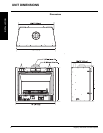
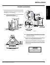
Diagram 1
A) Flat on Wall
B) Flat on Wall Corner
C) Recessed into
Wall/Alcove
D) Corner
HEAT RELEASE KIT
The Heat Release Kit expels warm air from
the fi replace to the outside of the building,
allowing the fi replace to be operated with less
heat entering the room. The kit may be used on
either the left or right side.
See Heat Release installation manual for
complete details and clearances from side
only.
7) Install standard and optional features. Refer
to the following sections:
a) Brick Panels
b) Log Set
c) Standard Flush Door
d) Flush Louvers
e) Finishing trim
f) Remote Control
8) Final check.
Before leaving this unit with the customer, the
installer must ensure that the appliance is fi ring
correctly and operation fully explained to
customer.
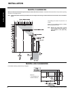
Floor Mounted Fireplace
Raised Fireplace
The HeatWave Duct Kit has different
clearance and framing requirements,
check the HeatWave manual for details.