


Regency
®
P40 Direct Vent Gas Fireplace 33
INSTALLATION
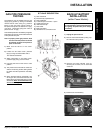
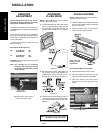
WIRING DIAGRAM
CAUTION: Label all wires prior to disconnection
when servicing controls. Wiring errors can
cause improper and dangerous operation.
A receptacle is provided on the left hand side
of the unit. 120 Volt AC power must be wired to
the receptacle and the control module plugged
in for the unit to operate fully. The front and
rear burners will operate on low, when the unit
is running on battery back-up.
(Do not cut the ground terminal off under
any circumstances.)
Caution: Ensure that the wires do not touch any
hot surfaces and are away from sharp edges.
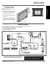
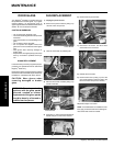
INSTALLATION
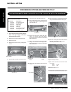
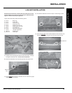
FINISHING TRIM
NOTE: Install Finishing Trim prior to installing
the Flush Door and Louvers.
1) Install the Finishing Trim sides as shown
in diagram 1, line up the holes in the side
trim with the holes in the fi rebox side.
2) Secure with 2 screws per side.
3) Loosen the 3 screws in the top inside edge
of the fi rebox.
4) Slide the Finishing Trim Top over the Side
Trim pieces and fi t the bottom bracket slots
over the screws. Tighten the 3 screws to
secure.
Diagram 1