


Regency
®
P40 Direct Vent Gas Fireplace
22
INSTALLATION
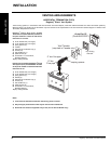
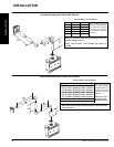
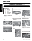
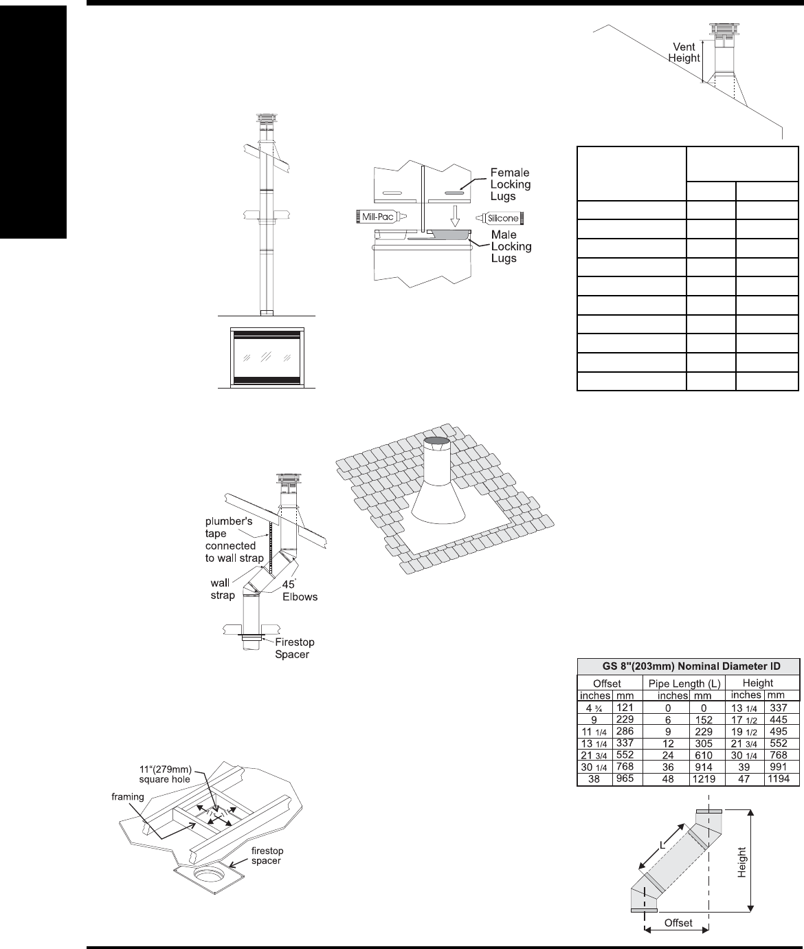
6) Continue to assemble pipe lengths.
Note: If an offset is necessary in the attic
to avoid obstructions, it is important
to support the vent pipe every 3
feet (0.9 meter), to avoid excessive
stress on the elbows, and possible
separation. Wall straps are available
for this purpose
(Diagram 2).
Galvanized pipe is desirable above the roofl ine
due to its higher corrosion resistance. Continue
to add pipe sections through the fl ashing until
the height of the vent cap meets the minimum
height requirements specifi ed in Diagram 5 or
local codes. Note that for steep roof pitches,
the vertical height must be increased.
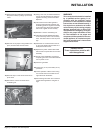
Diagram 3
Note:
Apply sealant "Mill-Pac" to inner pipe and
high temp silicone sealant to outer pipe on
every twist-lock joint.
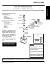
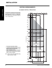
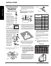
UNIT INSTALLATION
WITH VERTICAL
TERMINATION
(Rigid Vent Systems)
1) Maintain the 1-1/4"
(32mm) clearances
(air spaces) to
combustibles when
passing through ceilings,
walls, roofs, enclosures,
attic rafter, or other nearby
combustible surfaces. Do
not pack air spaces with
insulation. Check "Venting
Arrangemnt - Vertical
Termination" section for
the maximum vertical
rise of the venting system
and the maximum
horizontal offset
limitations.
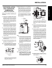
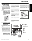
2) Set the gas appliance
in its desired location.
Drop a plumb bob
down from the ceiling to the position of the
appliance fl ue exit, and mark the location
where the vent will penetrate the ceiling.
Drill a small hole at his point. Next, drop a
plumb bob from the roof to the hole
previously drilled in the ceiling,
and mark the spot
where the vent will
penetrate the roof.
Determine if ceiling
joists, roof rafters
or other framing will
obstruct the venting
system. You may
wish to relocate
the appliance or to
offset, as shown
in Diagram 2 to
avoid cutting load
bearing members.
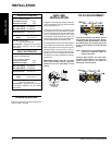
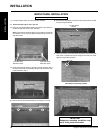
3) A Firestop spacer must be installed in the
fl oor or ceiling of every level.
4) Assemble the desired lengths of pipe and
elbows. Ensure that all pipes and elbow
connections are in the fully twist-locked
position and sealed.
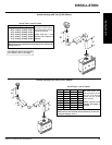
Diagram 4: The upper half of the fl ashing is
installed under the roofi ng material and not
nailed down until the chimney is installed.
This allows for small adjustments.
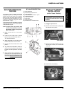
5) Cut a hole in the roof centered on the small
drilled hole placed in the roof in Step 2. The
hole should be of suffi cient size to meet
the minimum requirements for clearance
to combustibles of 1-1/4"(32mm). Slip the
fl ashing under the shingles (shingles should
overlap half the fl ashing) as per Diagram 4.
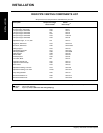
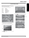
Offset Chart
A poor draft, or down drafting can result from
high wind conditions near big trees or adjoining
roof lines, in these cases, increasing the vent
height may solve the problem.
7) Ensure vent is vertical and secure the base
of the fl ashing to the roof with roofi ng rails,
slide storm collar over the pipe section and
seal with a mastic.
8) Install the vertical termination cap by twist-
locking it.
Note: Any closets or storage spaces, which
the vent passes through must be
enclosed.
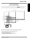
Diagram 5
Roof Pitch
Minimum Vent
Height
Feet Meters
fl at to 7/12 2 0.61
over 7/12 to 8/12 2 0.61
over 8/12 to 9/12 2 0.61
over 9/12 to 10/12 2.5 0.76
over 10/12 to 11/12 3.25 0.99
over 11/12 to 12/12 4 1.22
over 12/12 to 14/12 5 1.52
over 14/12 to 16/12 6 1.83
over 16/12 to 18/12 7 2.13
over 18/12 to 20/12 7.5 2.29
Diagram 2
INSTALLATION