50 C1566M-C (10/05)
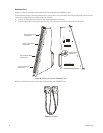
MONITOR OUTPUT CARD (CM9780-VMC) DETAIL
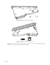
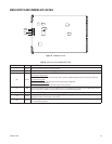
Figure 42. CM9780-VMC Card
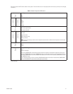
Table I. Monitor Output Card (CM9780-VMC) LEDs
Front Panel Label Color When LED is on or blinking
+ Green The +5 VDC power source is functioning properly.
- Green The -5 VDC power source is functioning properly.
HB Amber
The CPU is active; this “heartbeat” LED blinks at a different rate, according to the current activity:
Primary VMC—0.25 Second: Downloading
The primary VMC card blinks at a quarter-second rate while updated software is downloading from a PC connected to
the RS-232 COM port on the rear panel.
Secondary VMC—0.25 Second: Receiving
The secondary VMC card blinks at a quarter-second rate when it is receiving files from the primary VMC card.
0.5 Second: Boot ROM
The primary and secondary VMC cards blink at a half-second rate when in normal boot ROM mode.
1.0 Second: Normal Operation
The primary and secondary VMC cards blink at a one-second rate during normal operation.
RX Amber
Blinks when communication is active between the MXB and either the CC1 or a PC (through the RS-232 COM port; for
system software upgrade).
MP Amber
Blinks when communication is active between the primary VMC card and the other cards (secondary VMC card and
VCC cards). This communication occurs during normal system operation, as switching commands are sent and polled.
FP Amber Blinks once to indicate that the characters have been enabled for monitor display. This is the third initialization step.
CP Amber Blinks once to indicate that the CPU support chip has been configured. This is the second initialization step.
BP Amber Turns on during the boot sequence (the first initialization step), and turns off when initialization is complete.
AMBER
DIP SWITCH
GREEN


