30 C1566M-C (10/05)
SYSTEM DEVICE CONNECTIONS
1. Turn off the power to all system devices and disconnect all power line cords while connecting system devices.
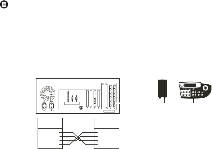
2. Complete the following steps to connect one or more CM9760-KBD system keyboards.
a. Connect the keyboard to the CM9505-UPS using the straight cable supplied with the keyboard.
b. Connect the CM9505-UPS to one of the RS-422 COM ports on the CC1 using the 6-foot (1.8 m) reversed data cable supplied with the
keyboard. Refer to the Data Connections section and your Port Assignments insert for directions on which port to use for each
keyboard.
c. Refer to the CM9760-KBD Keyboard Installation/Operation manual for detailed instructions.
Figure 21. Connect the CM9760-KBD to the CM9700-CC1
3. Connect a VGA monitor to the CM9700-CC1, as shown in Figure 22. This monitor displays the CC1 system diagnostic screen, as shown in
Figure 26.
4. Connect the PS/2 keyboard to the PS/2-to-AT keyboard adapter, and then connect the adapter to the CM9700-CC1, as shown in Figure 22.
5. Complete the following steps to connect a PC to the CM9700-CC1. Refer to Figure 22 and Figure 23.
a. Using a null modem cable (user-supplied), plug one end into the DB9 COM 1 port on the PC.
b. Plug the other end of the cable into the DB9 COM 1 port on the CC1. This port is configured at the factory for use with the
CM9700-MGR and RS-232 communication.
NOTE: CM9760-KBD software version 8.03 or higher is required.
CM9700-CC1
CM9760-KBD
CM9505-UPS
POWER SUPPLY
CM9700-CC1
RJ45-PIN-OUTS
PIN 1
PIN 2
PIN 7
PIN 8
=
=
=
=
TX+
TX-
RX-
RX+
PIN 1
PIN 2
PIN 7
PIN 8
=
=
=
=
TX+
TX-
RX-
RX+
CM9760-KBD
RJ-45 PIN-OUTS


