10 C1566M-C (10/05)
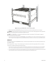
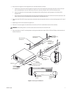
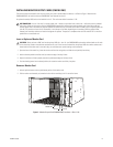
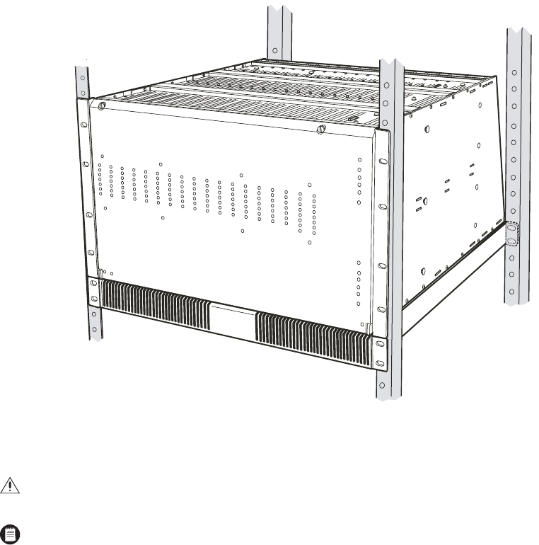
Figure 2.
Mounting the CM9780-MXB on Top of the Mounting Baffle
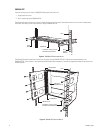
3. (Optional) Install additional CM9780-MXB mounting trays and matrix bays to the side of and below the first unit, as necessary.
4. Use the RJ-45 data cables supplied with each CM9780-MXB to connect the MXBs to the CC1. Refer to the
Data Connections
section and
the
Port Assignments
insert (supplied with the System 9780 documentation) for directions on which port to use for each MXB connection.
CM9700-CC1
The CC1 must be located near the CM9780-MXB matrix bays. The maximum distance between the CC1 and the matrix bays should be no more
than 4,000 feet (1,219 m).
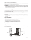
The CC1 occupies 4 RUs or 7 inches (17.18 cm) of vertical space in a universal mount. Allow 1 RU of space above the CC1 for air circulation.
To install the CC1 complete the following steps and refer to Figure 3:
1. Attach one ear to each side of the CC1 using three 8-32 x 0.250-inch pan head screws for each side. Attach each ear so that the slotted
holes in the ear are positioned toward the front of the CC1 and the tapered ends of the ear are positioned toward the rear of the CC1.
2. For each set of support rails, attach the front-mounting support rail to the rear-mounting support rail using three 8-32 x 0.375-inch pan head
screws and washers for each set. Leave the screws loose until the support rails are attached to the rack.
WARNING:
Always install equipment starting from the bottom of the rack frame or cabinet. Installing equipment from the top down will
make a rack or cabinet top heavy and could cause the equipment to tip over.
NOTE:
Each CM9780-MXB has a unique label for identifying the bay location in the installation. This ID information is important in
ensuring correct video and data connections.


