


C1566M-C (10/05) 31
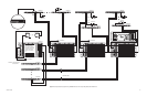
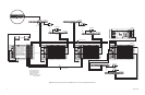
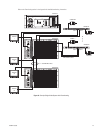
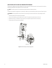
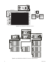
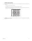
Figure 22. CM9700-CC1 Device Connections
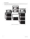
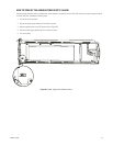
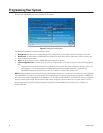
Figure 23. CM9700-MGR PC Pin-Out Detail
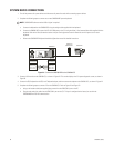
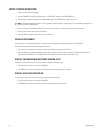
6. Install any additional system peripheral devices. Refer to the manuals for the individual devices for instructions. Refer to the Data
Connections section and your Port Assignments table for directions on which port to use for each device.
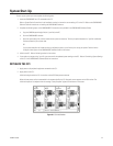
7. Connect all power line cords to the equipment. Do not turn on the power until the installation is complete. Refer to the System Start-Up
section.
CM9700-CC1
PS/2 KEYBOARD
VGA MONITOR
CM9700-MGR
PIN 3 (TX) PIN 2 (RX)
PIN 2 (RX) PIN 3 (TX)
PIN 5 (GND) PIN 5 (GND)
CM9700-MGR
PC COM PORT
CM9700-CC1
COM 1/COM 2
DB9 FEMALE DB9 FEMALE
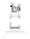
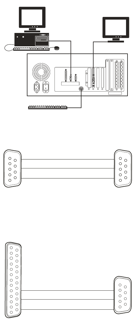
PIN 2 (TX)
PIN 2 (RX)
PIN 3 (RX) PIN 3 (TX)
PIN 7 (GND) PIN 5 (GND)
RS-232 CABLE
DB25 FEMALE DB9 FEMALE
CM9700-MGR
PC COM PORT
CM9700-CC1
COM 1/COM 2
RS-232 CABLE