


©
National Instruments Corporation 3-1 VXI/VME-PCI8022 for Solaris
Chapter
3
VXI-MXI-2 Configuration
and Installation
This chapter contains the instructions to configure and install the
VXI-MXI-2 module. This chapter applies only if you ordered the
VXI-PCI8022 interface kit. If you ordered the VME-PCI8022 kit, skip
this chapter and refer to Chapter 4, VME-MXI-2 Configuration and
Installation.
Caution:
Electrostatic discharge can damage several components on your
VXI-MXI-2 module. To avoid such damage in handling the module,
touch the antistatic plastic package to a metal part of your VXI chassis
before removing the VXI-MXI-2 from the package.
Configure the VXI-MXI-2
This section describes how to configure the following options on the
VXI-MXI-2.
• VXIbus logical address
• VXIbus Slot 0/Non-Slot 0
• VXIbus local bus
• VXIbus CLK10 routing
• Trigger input termination
• MXIbus termination
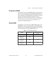
• Configuration EEPROM
• Onboard DRAM
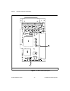
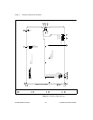
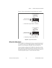
Figure 3-1 shows the VXI-MXI-2 as it would appear when facing the
right side cover. The drawing shows the location and factory-default
settings of most of the configuration switches and jumpers on the
module. Notice that switch S6 (called out as number 8 in the figure)
is accessible only by removing the front cover.
!