


Failure to properly center the brake and obtain uniform lining contact results in localized heating
and, ultimately, reduced torque, which can cause injury or death.
Chapter 6: ADJUSTMENT – Warnings and Cautions
Protect against the possibility of movement due to the effects of gravity, wind or other source of
energy, which has the potential to create a hazard when the brake is being worked on or is
removed entirely.
If the brake is arranged to operate in manual mode, the actuator “reserve stroke” must be
monitored and adjusted to be within the range of 30 to 35% of full stroke with the brake applied.
An actuator reserve stroke of zero will result in total loss of brake torque.
Under no circumstances should the brake be allowed to function with zero reserve stroke. Such
operation results in loss of load control, which can result in injury or death.
Always replace the caps on the actuator once adjustments are complete. This will prevent entry
of contaminants.
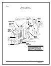
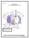
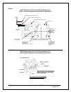
The optional automatic adjustment mechanism uses a one-way clutch to adjust brake shoe
clearance. It is located inside the clutch ring (R) shown in Fig.2A. Never disassemble this clutch.
Incorrect reassembly will render the auto-adjust feature inoperative. This can lead to loss of load
control and result in damage, injury or death.
If it is necessary to use a wrench to adjust the reserve stroke of a brake with auto-adjust, first
withdraw the drive pin (E) shown in Fig.2A and rotate the mechanism in the required direction. Do
not disturb the factory set pre-load, which is secured by set screws in nut (F). Releasing the
brake will take the load off of the brake rod thread and make it easier to turn.
The two setscrews used to lock nut (F), see Fig. 2A, to the clutch drive shaft, are factory set. Do
not loosen these setscrews or change the position of nut (F) with respect to the assembly. Failure
to observe this warning can cause the automatic adjustment feature to become inoperative. This
can lead to loss of load control and result in damage, injury or death.
Chapter 7: ELECTRICAL DETAIL – Warnings and Cautions
The actuator motor must be connected to its supply through a flexible cable or sealed flexible
conduit. This is required to ensure that contaminants will not enter the motor through the wiring
and junction box.
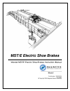
8/17/2006 Page 5 of 33 MST/E Electric Shoe Brakes Manual
560022-R6