Chapter 7.0: Electrical Detail
7.1: Operation of the actuator is not dependant of the direction of motor rotation. The cable leads can
be connected to the U1, V1 and W1, (T1, T2, T3), terminals in any phase sequence.
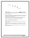
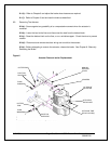
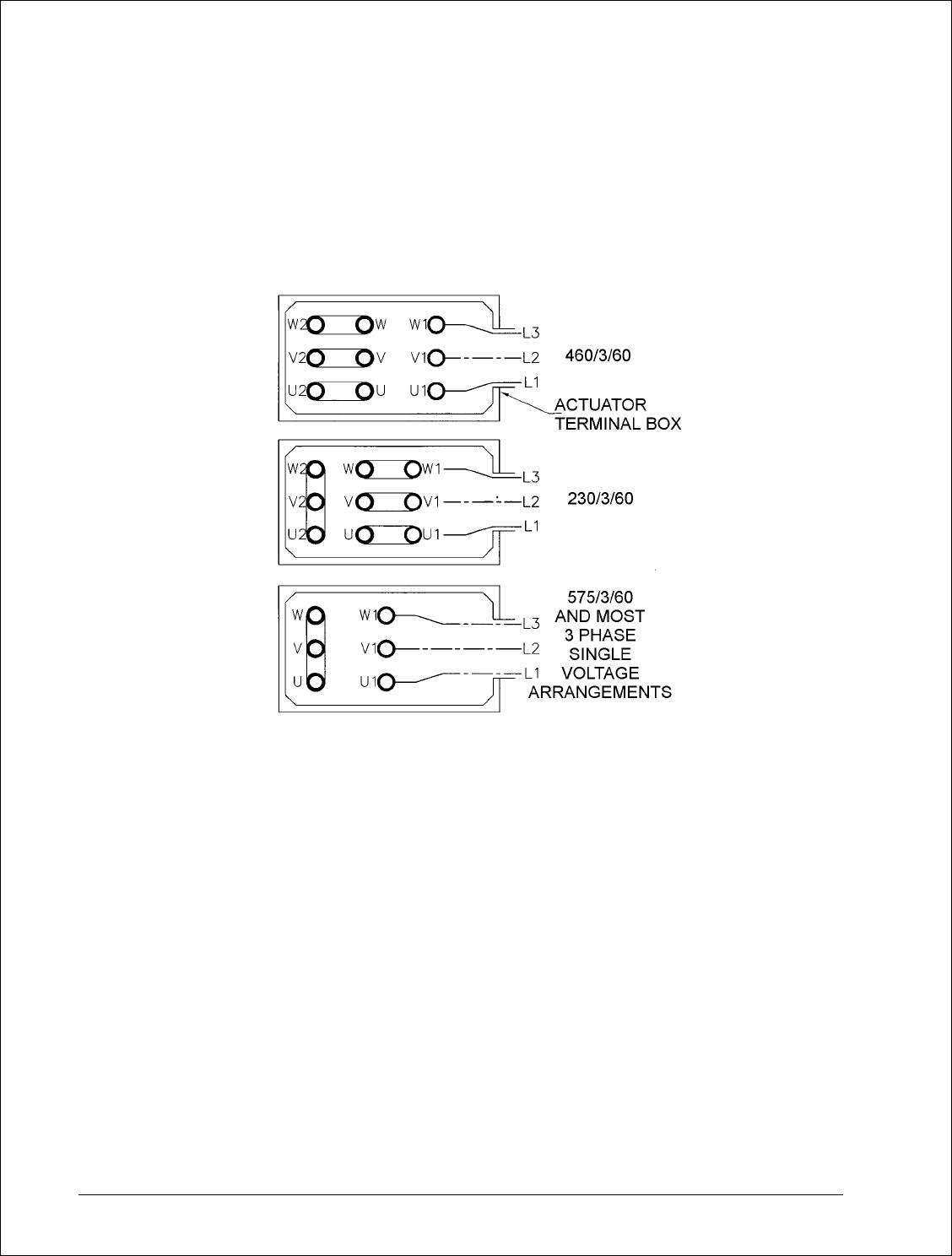
Figure 4
Electrical Connections
7.2: The motor leaves the factory already arranged for the specified voltage, which is also shown on
the nameplate.
7.3: If the motor was specified for a nominal 460 volts supply, it will be connected with nine terminals
and the links arranged as shown in Fig. 4. If at some future date the motor is required to operate
from a 230 volts supply, re-arrangement of the links is required as shown.
7.4: When specified for operation on 575 Volts or other single voltage, it will be connected with six
terminals, the links arranged as shown in Fig. 4. The winding will not be capable of re-connection
for any other voltage.
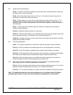
7.5: Explosion Proof actuators are only arranged for the terminal voltage shown on the nameplate.
Three terminal posts will be visible when the cover plate is removed under the required
conditions. No provision is made for external re-connection to any other voltage.
8/17/2006 Page 23 of 33 MST/E Electric Shoe Brakes Manual
560022-R6
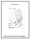
7.6: A wiring diagram showing the possible terminal link arrangements is fastened inside the actuator
terminal box cover.


