


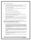
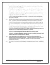

5.7: Type MST/E brakes can also be wall mounted with the brake wheel shaft vertical. Again this
requires the actuator hydraulic section filler plug to be at the highest point possible with the
actuator horizontal. For this mounting arrangement both equalizing bolts may be required to
ensure equal shoe clearance.
5.8: For any other mounting arrangements consult factory.
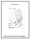
5.9: The brake assembly must always be square and aligned to the brake wheel within a maximum of
± 1/32 inch, in three axes (horizontal, vertical, and longitudinal).
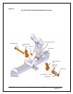
5.9.(a): Adjust the brake support bracket to achieve the specified horizontal and longitudinal
alignment. For best performance, the brake base should be flat and parallel to the wheel rim or
motor shaft. It may be necessary to release and re-apply the brake pressure several times to
achieve optimum alignment. Shim under the brake base for the vertical alignment.
5.9.(b): When the brake assembly is correctly aligned and clamped to the wheel, check the
securing bolt clearance in each of the brake base holes. There must be clearance in the base
and through the brake support bracket to allow minor adjustments. Be sure that the brake shoes
are still aligned parallel to the face of the brake and that each brake shoe is fully secured to its
link arm.
5.9.(c): With the brake fully applied, verify that the shoes are centered on the wheel face and that
lining contact is within adequate bedding range.
5.9.(d): When the brake is correctly aligned in all three axes, tighten the brake mounting bolts
and re-check the alignment.
8/17/2006 Page 15 of 33 MST/E Electric Shoe Brakes Manual
560022-R6
5.10: Connect the actuator to the electrical supply using a flexible, sealed conductor, suitable for the
rated temperature. Use type “S0”, or higher temperature, cable. The actuator must be allowed
few degrees of movement without the risk of dirt or moisture entering the terminal box. Chapter 7
provides all necessary electrical details.