


9.2.(f): Secure or support the actuator before attempting to remove the pivot pins.
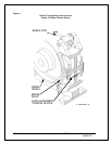
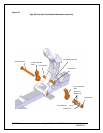
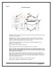
9.2.(g): Refer to Fig. 6: remove the cotter pins and withdraw the pivot pins attaching the actuator
to the brake body.
9.2.(h): Remove the complete actuator using appropriate lifting devices.
9.2.(i): Should service be required, return the actuator to Magnetek for repairs.
9.3: Re-Installing The Actuator
9.3.(a): Verify adequate means are still in place to protect unexpected movement when the
actuator is replaced.
9.3.(b): Position the actuator within the lever and attach to the base. Use a lifting device as
necessary.
9.3.(c): Attach and secure the actuator using the correct pivot pins, etc. Check for wear prior to
re-fitting, Fig. 6.
9.3.(d): Refer to Chapter 6 and adjust the reserve stroke as required.
9.3.(e): Refer to Chapter 6 and adjust the torque as required.
9.3.(f): Refer to Chapter 6 and adjust the brake shoe clearance as required.
9.3.(g): Re-connect the actuator wiring, as required, and replace the terminal box cover.
9.3.(h): Refer to Chapter 8; bed and test the brake as described.
9.4: Re-lining The Brake Shoes
We do not recommend that shoes be re-lined in the field. New bonded shoe assemblies
can be ordered as repair parts. Factory rebuilt shoes are also available from Magnetek.
Under this program, credit will be allowed for old shoes in usable condition.
9.5: Removal and Installation of Motor and Brake Wheel as an Assembly
9.5.(a): Quick replacement of the drive motor and brake wheel, as an assembly, can be
accomplished with minimum disturbance to the brake.
9.5.(b): Disconnect, lock out, and tag out the disconnect switch that feeds this equipment to
prevent power from being applied while service is being performed.
9.5.(c): Remove both shoe assemblies as described under the topic, “Replacing the Brake
Shoes”. If the shoes will not be replaced as part of this work order, identify the shoes in order
that they can be re-fitted without having to be re-bedded.
9.5.(d): Swing the entire brake rod assembly clear to permit unobstructed vertical withdrawal of
the brake wheel without damage.
9.5.(e): Remove the motor and brake wheel by lifting straight up until the wheel clears the brake.
9.5.(f): Install the motor and brake wheel by lowering it into place.
8/17/2006 Page 29 of 33 MST/E Electric Shoe Brakes Manual
560022-R6