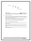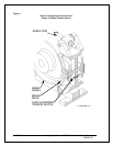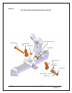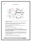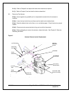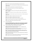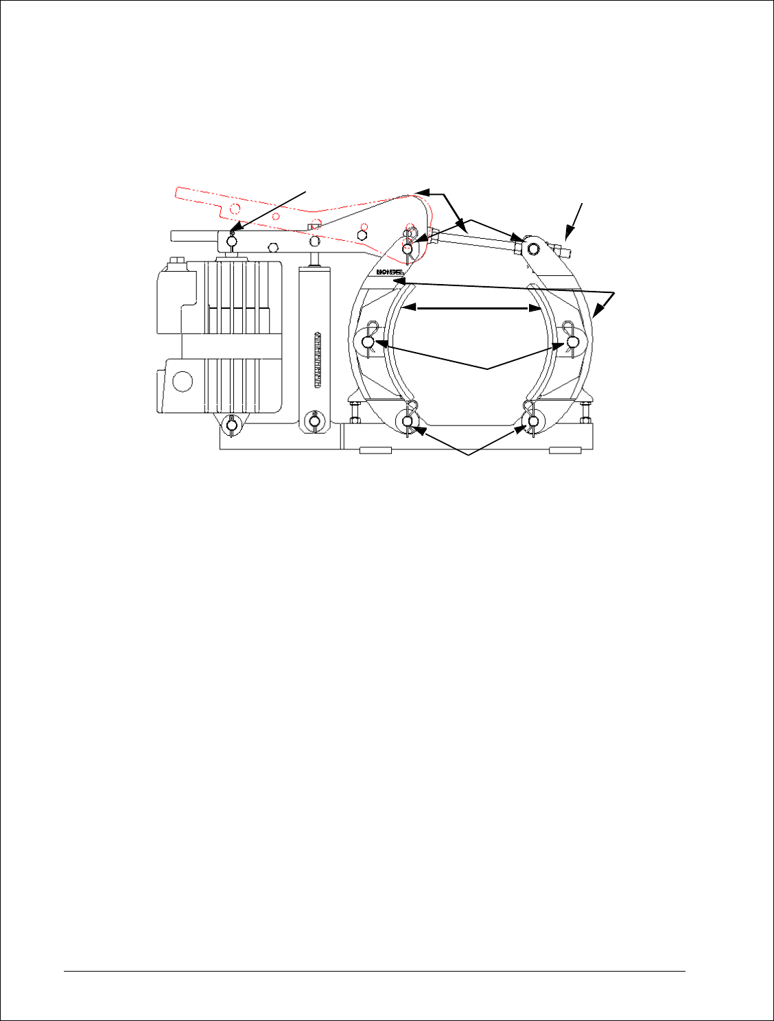
Figure 5
Brake Shoe Removal
9.1.(a).(xii): Before starting shoe installation, check that the brake surface of the wheel is clean
and free from oil and grease.
9.1.(a).(xiii): Next, verify that the lining surface will be true to the wheel when the shoe is
installed. Carefully check lining contact with the wheel. Remove any high spots with emery
paper to ensure 60% contact between the lining and the wheel.
9.1.(b): Ensure adequate clearance will be available and install the replacement shoe
assemblies in the reverse order.
9.1.(c): Replace all pivot, cotter and hitch pins.
9.1.(d): Re-apply the brake and make all adjustments covered in Chapter 6.
NOTE: The brake can be damaged if the brake shoes are not accurately aligned. Do not
operate the brake unless the brake shoes are in their normal position and all pivot, cotter
and hitch pins are fully installed.
9.1.(e): Newly lined shoes seldom fit perfectly with the contour of an existing brake wheel,
particularly if the wheel is worn or undersized. If the brake has been moved, realignment of the
brake with the wheel may be necessary. Refer to the topic “Brake Installation” for the correct
alignment and bedding procedure.
9.1.(f): Refer to Chapter 6 and adjust the reserve stroke as required.
9.1.(g): Refer to Chapter 6 and adjust the torque as required.
8/17/2006 Page 27 of 33 MST/E Electric Shoe Brakes Manual
560022-R6
(1)
(3)
(4)
(5)
(6)
(8)
(7)
(2)


