6.5.(a).(iii): The correct linings are fitted.
6.5.(a).(iv): The linings are in good condition and bedding is completed.
6.5.(a).(v): The brake wheel is aligned and in good condition.
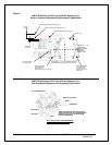
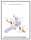
6.5.(b): Torque adjustment for Mondel MST/E brakes is adjustable on site. Tighten or loosen
screw (B), see Fig. 2, to set the torque within the prescribed range shown on the scale. The
torque setting is obtained by matching the top of the spring-block to a line on the spring scale.
6.6: Automatic Equalization Assembly
6.6.(a): The total available shoe clearance is determined by the active stroke of the actuator.
Distribution of the resulting clearance is determined by two factors.
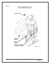
6.6.(a).(i): As the brake releases under power, the shoe nearest to the actuator has been biased
to open first. This is done during manufacture by inclining the actuator away from the nearest
shoe. (Fig. 2).
6.6.(a).(ii): Clearance provided to the nearest shoe is restricted by the (AE) mechanism located
on the base. The clearance between the friction bolt and holes in the base, through which it
passes, determines the “actuator side” shoe clearance.
6.6.(b): When the predetermined “actuator side” shoe clearance has been established, the
remaining clearance is transferred to the “non-actuator side” shoe.
6.6.(c): As lining wear occurs, the friction bolt in the (AE) mechanism is dragged to a new
location, to provide the reference point for the shoe clearance on the “actuator side” of the brake.
6.6.(d): The (AE) friction bolt mechanism is self-compensating after initial adjustments are
completed as follows:
6.6.(d).(i): Release the brake and, using a soft-faced mallet if necessary, force the actuator side
link away from the wheel. This will set the actuator side (inner) shoe to the maximum available
clearance.
6.6.(e): The actual clearance which will be allowed to the “actuator side” shoe is determined by
the difference in diameter between the friction bolt shank and the holes in the links, through which
it passes.
6.6.(f): The friction bolt assembly is pre-tensioned at the factory. DO NOT FIELD ADJUST. If
the friction bolt assembly is disturbed for any reason it can be retensioned as follows:
8/17/2006 Page 18 of 33 MST/E Electric Shoe Brakes Manual
560022-R6
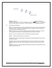
6.6.(g): Refer to Fig. 3a: Install friction bolt through Automatic Equalization arms and base. Add,
onto the end of the friction bolt, a stack of three Belleville washers in series, (as indicated below),
followed by a plain flat washer.


