


6.4: Actuator Stroke Adjustment
6.4.(a): When power is applied to the actuator the piston will be caused to extend. This will
compress the external spring and raise the brake lever to provide operating clearance between
the shoes and the wheel.
6.4.(b): When power is removed from the actuator, the spring will retract the lever until the shoe
pressure on the wheel prevents any further lever movement as the reserve stroke setting is
attained and the intended brake torque achieved.
6.4.(c): Brakes without Automatic Adjustment:
6.4.(d): Adjust the brake rod nuts until the brake release lever raises the piston rod to the
specified reserve stroke, (Table 2). Re-secure the brake rod nuts against the pivot block.
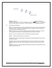
6.4.(e): Brakes with Automatic Adjustment:
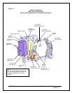
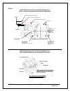
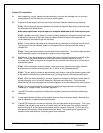
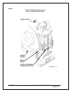
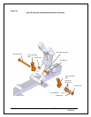
6.4.(f): To make initial adjustment before engaging the auto adjust (AA), refer to Fig. 2A and
withdraw pin (E). Rotate the mechanism by hand to decrease the brake rod length until the
linings contact the wheel and the brake lever begins to rise. Continue adjustment until the
required reserve stroke is about 1/8” less than specified. Re-engage pin (E) allowing the (AA)
mechanism to complete the final stage of the adjustment process. This will verify that the
mechanism is operating correctly.
6.4.(g): Energize the actuator several times until the rotating collar (R) is no longer turned by the
(AA) drive pin (E). Verify that the reserve stroke is still at the desired value per Table 2.
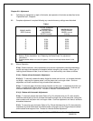
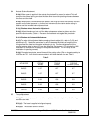
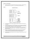
Table 2
ACTUATOR
MAX
STROKE
(inches)
ACTIVE
STROKE
(inches)
DESIRED
RESERVE
STROKE (inches)
Ed23/5
1.97
1.27
0.7
Ed30/5
1.97
1.27
0.7
Ed50/6
2.36
1.56
0.8
Ed80/6
2.36
1.56
0.8
Ed121/6
2.36
1.56
0.8
6.5: Torque Adjustment
6.5.(a): The rated torque, as shown on the nameplate, will be developed when the following
conditions are met:
6.5.(a).(i): The brake is applied and aligned properly.
8/17/2006 Page 17 of 33 MST/E Electric Shoe Brakes Manual
560022-R6
6.5.(a).(ii): The actuator stroke is correct.