


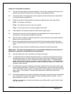
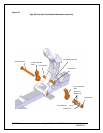
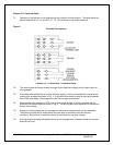
6.6.(g).(i): Install a castle nut, tighten nut until the flat washer is
FLUSH with the side of the
Automatic Equalization arm. Loosen or tighten the nut no more than 1/8 of a turn, only enough to
align the nearest cotter pin slot and hole. Install the cotter pin. This completes the assembly.
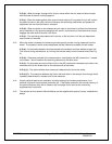
6.7: Shoe Clearance Adjustment
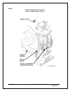
6.7.(a): The total available shoe clearance is determined by the active stroke of the actuator and
the brake lever ratio. Distribution of the resulting clearance is determined by the setting of the
active shoe clearance equalizing bolt (Fig. 2).
6.7.(b): Generally only one of the two equalizing bolts will be effective depending on the lever
ratio arrangement and subject to the brake being installed horizontally or vertically.
6.7.(c): The “active” equalizing bolt will be evident after energizing the actuator.
6.7.(d): To equalize the brake shoe running clearance:
6.7.(d).(i): Back-off both equalizing bolts and energize the actuator allowing the shoes to move
away from the wheel.
6.7.(d).(ii): Adjust the active side equalizing bolt to limit the travel of that shoe; this moves the
other shoe away from the wheel. Continue adjustment until wheel clearance is equal for both
shoes.
6.7.(d).(iii): Set the non-active side equalizing bolt so that shoe travel is not restricted; lock both
equalizing bolts with jam-nuts.
8/17/2006 Page 19 of 33 MST/E Electric Shoe Brakes Manual
560022-R6
(AE) ARM SIDE
CASTLE NUT SIDE