


9.1.(h): Refer to Chapter 6 and adjust the brake shoe clearance as required.
9.1.(i): Refer to Chapter 8; bed and test the brake as described.
9.2: Removing The Actuator
9.2.(a): Secure against any possibility of an unexpected movement when the actuator is
removed.
9.2.(b): Lower the load to the floor and disconnect the load from the bottom block.
9.2.(c): Reset the bottom block on the floor, or on a suitable support. Chock the drum to prevent
rotation.
9.2.(d): Disconnect and remove electrical wiring and conduit to the actuator.
9.2.(e): Before attempting to remove the actuator, release the brake. See Chapter 6: “Manually
Releasing the Brake”.
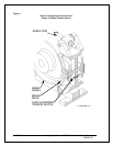
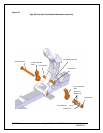
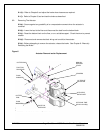
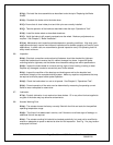
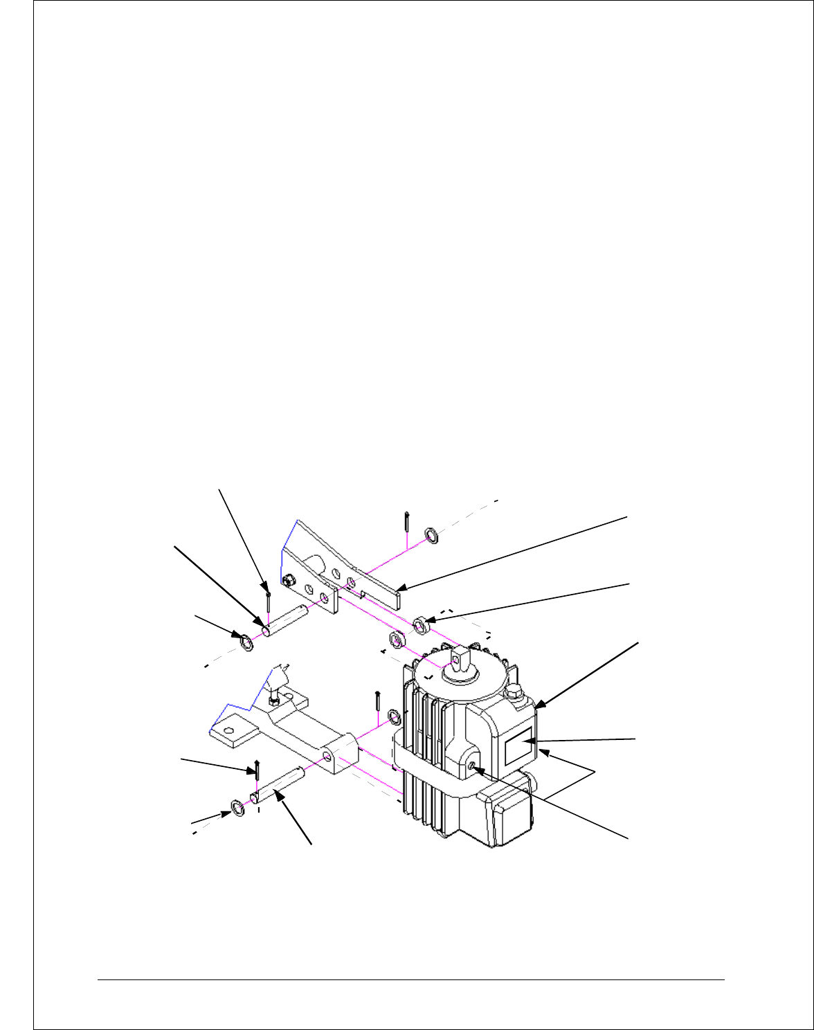
Figure 6
Actuator Removal and/or Replacement
8/17/2006 Page 28 of 33 MST/E Electric Shoe Brakes Manual
560022-R6
Figure 6:
ACTUATOR
SPACERS
MANUAL
RELEASE
LEVER
COTTER PINS
PIVOT PIN,
PLAIN
WASHERS
COTTER
PINS
PLAIN
WASHERS
PIVOT PIN,
FIXED END
Actuator Removal and/or Replacement
DRIVE END
OPTIONAL TIME
DELAY VALVE(S)
DATA PLATE
HY-THRUST
ACTUAT OR